Electron Engine ™
Printed Circuit Boards by Emissionlabs ®
- Tube Test System EE12. Introduction.
- Stand alone System, together with Power Supply EE11
- Tube Data Table
- Use EE12 with an existing tube tester (instead of Power Supply EE11).
- Typical Test sequence
- About the purpose of burn in.
- Fusing of the boards.
- Building instructions
- Options
Fault Finding with EE11 (Power Supply) and EE12 (Tubes Board)
Fault finding is not difficult, because the power supply and tube boards are separated. Also the build instructions are such that you can hardly make a mistake and not notice it. In case a defect, problems by itself are small, and not much can be badly damaged, because of the good fusing concept. But... a problem has to localised first. It is important to understand how this device works, before doing fault finding. That is why reading the following text first, is a good idea.
Some more about the working principle.
The working principle resembles some classical AC operated parametric testers, such as the Neuberger WE234, Metrix 310, and AVO Mk1...Mk4. However functions were added, or left away, to get the product we wanted here.
Bias method
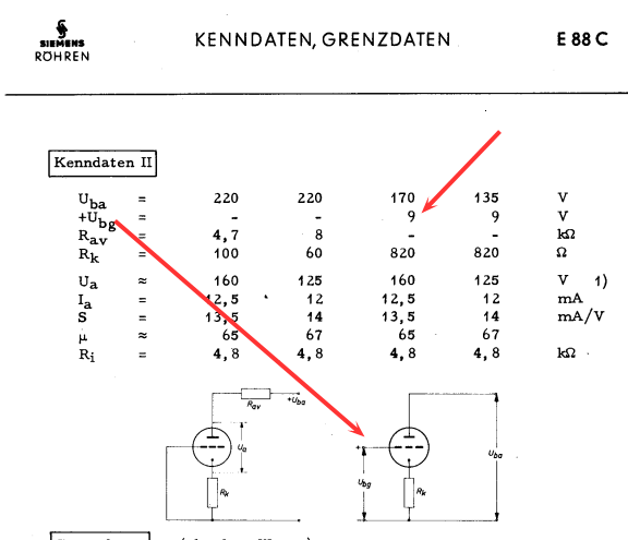
The bias method is in between auto bias and variable bias. Called mixed bias. This is in accordance with the data sheets of Siemens and Telefunken for high quality tubes, such as E88CC and D3A. So this is not something we invented here, but simply using the test method as described in the data sheet. And no, in the Telfunken data sheet is not written, E88CC has to be tested with fixed grid voltage. Testig with fixed grid voltage is WRONG, and you won't find that in any data sheet. In the Telfunken E88CC data sheet, is given the test circuit for mixed bais. It is just what we do here also, with this burn in device. Here is an example. It is done, by constructing an auto bias circuit first, but the grid is not grounded (as with auto bias), but connected to a fixed or variable DC voltage. This voltage can be positive or negative as well. In case it would be adjusted to zero volts, the tubes bias becomes classic auto bias. If changed to negative, the tube still would be in auto bias still, but now at lower current. If changed to positive, we can increase the current, and we can go as far with this, as the voltage drop across the bias resistor. (Above that, the tube would have positibe grid voltage, which is not allowed, and the White LED will burn very bright, showing this fault condition). So positive or negative control voltage, this tester can do both, and actually to very high negative values. Meaning we can fully cut off the current of the tubes, which is a very useful test. Also we can increase the current so much, we would even drive the tubes with positive grid voltage. Though this appears to work, most tubes are not intended for it. If the grid current LED begins to burn, we are above 500uA for the whole test board, and above that it is not desirable. Actually the prevention of grid current results automatically, when we bias the tubes as they should, by the test data on this website. Like when the test table says to use 2mA, you could set the tubes 4mA still, but that might cause grid current, making the test result invalid. Also possibly damaging the tubes. So doing that is not a good thing.
For more sensitivity, you may consider to calibrate the triggering of the grid current LEDs to 250uA instead of 500uA, but that will also make the LEDs burn less bright. Alternatively, add a sensitive uA meter in the grid circuit, in case you are interested in that. The power supply board has prepared connections for this. Described under Options.
Precise test values.
The question comes often: What is the exact values for the tubes I am testing? Now first, nobody can tell you this, because all data sheets say nothing about this at all. These do give average values, which applies only for a lot 100 tubes, but a specific tube may have large deviation of this, and be 100% good. This deviation, manufacturers never tell what it is. So you must look at what we know already. We find in reality +/- 30% for NOS tubes, and new made tubes are +/- 50% or more, and they say it is normal. So specifically require the average values make only sense when you test many tubes, and you need to know the average of the lot indeed. So then you can complain to the manufacturer, and say for instance: Over an average of 100pcs, your tubes are 20% too low. Yet it would be silly to buy 2 tubes, call "2" a valid lot size, and complain they are 20% too low.
Second, it would be beyond the purpose of this tester to test only a single tube. Besides, there is a MUCH BETTER way to find out tube quality still. All tube factories of the old days did it that way, to initially sort out the bad from the good tubes. The method is: Just test several tubes of one type all together.
For SURE you can identify one bad tube, if you know the other 5 or 10 are good, without having to know it's data. Mind, this tester sweeps the tube through it's curves! So a tube may be good at one voltage, but not at the other. So sweep it up and down the curves is almost a "must" to do this with AC. Long ago, the Hickok company defined that as a standard method for most of their tube testers.
Moreover you should vary the grid voltage, to see if an unknown tube reacts the same as some reference tubes. The same applies even more for matching and balancing. If you test a pair of tubes only, and one behaves different from the other, without having to know anything about the matching method, you can already say: This is NOT a good pair. It gets even a better diagnosis, when also adding a pair of sure known to be good tubes as well. So simply test four tubes at a time. Or stuff the whole test board with similar tubes, and compare an unknown tube with all of these. And frankly, what other tube tester can do this....?!

Here us a picture of such a device, as used in the EI factory (now closed). The brown parts are (empty) tube sockets. The light bulbs are used as a current indicator, and as a fuse at the same time. So with just one quick look, the operator can pick out a single bad tube, from such an array of 200 tubes. This works on AC voltage. We go essentially the same way with our burn in device, just we use LEDs to measure the tube current more precisely. Moreover we do not use light bulbs as a fuse, but we use a self resetting thermo fuse on each group of five tubes.
Fault Finding
- This is not a hardware fault, but an operator error: When testing 6,3V tubes, you always need to test two of the same in a row, of each board. So you can not put two tubes in the top row (V1+V6) and only one tube in the next row (V2 only). That would serialize the heaters not right, and tubes do not burn on 6.3V any more. This is however possible with 12,6V tubes.
- In case you activated a thermo fuse. They are self re setting, but this takes a few minutes cooling. These have limited switching cycles, appr 50x, which is more than enough because they only activate on really bad situations. ,
- The Blue LED stays off. Possible reason: There is no high voltage on the EE12 board. If the Red-green LEDs are off too, the power supply is not working. If one is burning however, the problem is with the tubes board or the wiring. With "anode on" check for appr 200V DC, on Ua vs Gnd. If this voltage is present however, perhaps the micro fuse is blown. Or, in the building phase, the blue LED or diode 1N4007 was mounted reversed. If that was so, the LED must be replaced, even when it still seems to work, it may be pre damaged by the reverse voltage, and it may fail later. For safety this LED is important.
- Some LED meters can not be set to zero current, though you believe the tubes under test are GOOD. This will be verified by putting that tube in another socket. If the problem seems to be related to the tube socket, this means the grid capacitors were damaged. This can only happen when there was a short from the anode to the grid circuit. The most common cause is an electrical short during measurements on the tester. In some cases, a tube had a short from anode to grid, but this is rare and probably not the cause. Or, insert a tube this tester was not made for, will also cause it. The grid capacitors are NOT the ones underneath the socket. Those underneath only connect the internal shield to ground, in case a tube has that. The grid capacitors are on the components side of the board, and there is one per tube socket. In case one was damaged, all capacitors of the whole tester need to be replaced. The other ones that may seem good, were pre damaged and will fail later, or cause already now other errors. So again, this fault condition can be seen if always the same tube socket will fail to cut off the anode current fully.
- A damaged tube socket. Try to de-solder it, may damage the board. Better is cut off the contacts with a side cutter and then the pins can be soldered out one by one.
- If the Grid current LEDs work strange, or not at all. In that case do a re-calibration of those LEDs, and you will notice if that circuit is good or bad. If good, the cause is not in the EE12 board. However if you find one of the two burned out, you need to replace both of them.
- The grid voltage potentiometer. This is a 10-turns helicoil type, 100k. If rotated to the "stop" with force, these may damage. It can happen during mounting of the knob. Most of the time there is a "funny" spot then, which you can feel at a position, while slowly rotating it. Such a potmeter should be replaced, even when it seems to work, it will give problems later.
- One half (left or right side) of a tube board can not make the Anode current LEDs burn. This is a problem with the self-resetting thermo fuse. In case the fuse is hot, there may be a short on the board perhaps. These thermo fuses can no be used very many times. It is hard to say how often, but it us something like 50 times or more. During normal overload (if you call that normal....) They will not activate so quickly.
- The Red LEDs burn not uniform, when expected. This may have to do with positive grid current. Some tubes, like E88CC do not like this, and are also not made for this. This will cause a high frequency effect, a very short "ringing" effect. These are a few short pulses, it is not an oscillation, but it does give more anode current as expected. This ringing is quite tube dependant, and due to PCB wiring and your own wiring, some sockets seem to have it more than others. However it is an operating error, if the tubes are set at higher current as recommended in the test data. If so, the PCB (integrated) coils provide not enough protection, and this problem may occur. Moreover, when you can see, you are short before the limit of grid current (LEDs burn above 500uA for the whole board) this is another hint, simply reduce the anode current, and the problem will be gone. In case there is doubt, a particular LED may be damaged, do not just replace the LEDs, but do the LED test, as described in the general building text. This will then quickly unveil any bad LEDs if there are some. In the building text, we recommend to do this for only one tube socket, but for fault finding with LEDs, you can better do this for the whole board at once. For this, stick a short piece of appr 0.8 ....1mm wire into pins 3 to 8 into of each socket. Then connect those 10 wire pieces together, and do the LED tests as described in the building instructions.