Electron Engine ™
Printed Circuit Boards by Emissionlabs ®
- Tube Test System EE12. Introduction.
- Stand alone System, together with Power Supply EE11
- Tube Data Table
- Use EE12 with an existing tube tester (instead of Power Supply EE11).
- Typical Test sequence
- About the purpose of burn in.
 Fusing of the boards. (You are here)
- Building instructions
- Options
Fusing of the Boards
Errorz can happen. With all the testing of unknown tubes, there is always something which can go wrong, but the protection concept of the burn in system is good, and risk on damage is really low. The largest human risk is putting a non-testible tube inside, such as a pentode or a rectifier tube. Even then, chances it will only cost you a fuse, are good.
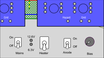
How the Socket Board EE12 is fused:
- Over-Current. Each board has two groups of tubes V1...V5, and V6...10, each with a thermal fuse of 80mA. Each group can deliver maximum 18Watt anode dissipation into the tubes, so 36 Watt for one board. So even though the whole board is thermal fused at 160mA, also the board will partially switch off when this 160mA is unevenly distributed. Since overload will likely distribute uneven between the groups, with one defective tube, this becomes very effective against errors.
- Temperature. Moreover, since those 80mA fuses work thermally, we have in addition also two positions on each board, which react to thermal overload, not matter where the heat comes from. So in a closed cage, given an overheating error would occur, also such boards will switch off which are close to 160mA already.
- Reset. Thermal fuses are slow, but more accurate than a melt fuse, and they are self resetting type. Still it should be avoided to use them as general switch-off devices. If they activate, find out what caused this, and prevent it. If one of the thermo fuses is open, this section (all left tubes, or all right tubes) will show no anode current any more, and the blue Hazard LED is still on. For a reset, the unit must be switched off 5 minutes with all switches and bias setting in the 'start' position
- Testing 6.3V tubes at 12.6V by mistake. I suppose at some moment this will happen to all of us. The excessive heater current at start up, will only blow the mains fuse, when all 30 tubes are inserted. Many times this will not be so, and the transformer just will supply 12.6V to 6.3V tubes, and the tubes will take damage from this quickly. So make a good habit of always starting with 6.3V, also with 12.6V types. Then, for 12.6V types, when you can see them beginning to glow even at 6.3V, or glow stays invisible, switch to 12.6V. Like this, over time you will develop a routine to visually check the heater glow.
- A grid short. First, a damaged electron tube is not a hard short, like a shorted transistor. A zero ohms short inside a tube, is hard to imagine. The anode current is limited by the emission of the tube, even in the case of a grid short which is the kind of short which sometimes happens. A grid short will increase the anode current very much and the anode LEDs of such a tube will sure catch your attention. Also such a grid short will lead to grid current and the white grid fault LEDs will light up very bright.
- Gassy tubes. A tube can have gas before, or develop gas during testing. Such a tube will show too little plate current, and if very bad, even light up the grid fault LED. Ideally the tube will self repair, when the gas is absorbed by the getter. If the gas is caused by a glass crack, the problem will only become larger during burn in. If a grid fault is indicated, then by removing the tubes one by one, the bad tube can be found. (Switch off before removing a tube). Monitor carefully if a small grid fault will go away, and if not, such a tube is a reject, and should not be further tested.
- Zero ohms short. This can only happen when a non-testible tube which was plugged in by mistake. For this, each Socket Board EE12 has a 160...250mA melt fuse, which will activate before the thermo fuses. When the melt fuse is blown, the blue hazard LED will be off. It is possible, depending on what is shorted, the tube grid will deliver or pull current via the gird connection, and in such a case, the grid fault LEDs light up, even though the anode voltage is off. That is because the grid has it's own power supply.
- Mains fuse. If all of the above fails, the power supply board has still a mains fuse. A short of the heater circuit will blow the mains fuse.
- An unintended fusing mechanism. Each tube (section) is grounded finally via the green LED. At a bad short, these 3mm LEDS do not short, but burn out. This is of course not intended as a real fuse mechanism, but it is good to know, this hidden safety exists.
- All in all, I found the Socket Board EE12 hard to damage and easy to repair.