Electron Engine ™
Printed Circuit Boards by Emissionlabs
- Tube Test System EE12. Introduction
- Stand alone System, together with Power Supply EE11
- Tube Data Table
 Use EE12 with an existing tube tester (You are here)
- Typical Test sequence
- About the purpose of burn in.
- Fusing of the boards.
- Building instructions
- Options and Support
DIY Burn-in System EE12 use with tube tester L3-3.
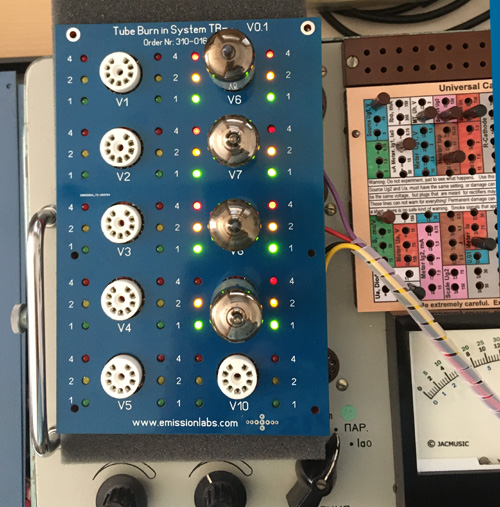
This is only shows how the tube tester L3-3 drives the board. It is the responsibility of the user to build a safe case around it.
Description:
Some tube testers, provide an adjustable power supply for Anode and Grid. These can be used with the EE12 board.
We have tested the Socket Board EE12 with the Kalibr L3-3, but it is expected to work with other testers as well, as long as these provide DC voltage, and enough heater current for the number of tubes under test. The Socket Board EE12 can simply be connected to the Octal or UX4 connector of the tester.
Bias method.
The Socket Board EE12 needs a control voltage for general bias, but this is not the actual grid voltage of the tubes. The grid voltage of the tester is used as control voltage for the board.
Prior to using with a tube tester:
- First you need to fit the EE12 unit into a safe housing, and attach Cable to them, with Octal (or UX4) connector at the other end, which you can take from on old tube, or we have also a new one for you. Do NOT use the EE12 without a safe, well isolated housing.
- We supply the appropriate test card for the Russian L3-3 tester.
- Set up the tester for anode voltage of maximum 250V, Grid from 0 to -30V, and the heater voltage for the tubes to burn in.
- Set the anode voltage to minimum, and the grid voltage to the most negative value.
- For the L3-3 tester: Connect an AC Voltmeter to the thick pins of socket #9, using banana plugs. This measures the heater voltage. Now switch on the tester, and first adjust the heater voltage as good as possible, by means of the mains calibration switch, called 'CETb'. This must be done with the tubes inserted.
- For all testers, check the heater voltage, and make sure you don't pull more heater current and anode current as the tester can do.
- The Power Supply EE11 for the Socket Board EE12, can work with 6.3V and 12.6V, so don't confuse this. If used with a tube tester, there is only ONE heater voltage. So 6.3V tubes are tested at 6.3V, 12.6V tubes at 12.6V etc.
- For the rest, the procedure is the same as with thePower Supply EE11, the tube tester just replaces this power supply.