Electron Engine ™
Printed Circuit Boards by Emissionlabs
- Tube Test System EE12. Introduction
- Stand alone System, together with Power Supply EE11
- Tube Data Table
- Use EE12 with an existing tube tester (instead of Power Supply EE11)
 Typical Test sequence (You are here)
- About the purpose of burn in.
- Fusing of the boards.
- Building instructions
- Options and Support
Typical Test Sequence - Short form
these drawings are just a possible way, to build this device. Everybody can do it his own way of course, but this arrangement of switches is a very safe one. It operates from the left to the right.
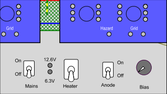 1. When the Device is off, set all switches in the downward position, and the bias to zero.
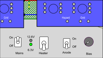 2. Mains on. The tubes heat now with 6.3V, regardless their heater voltage.
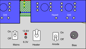 3. For 12.6V tubes, they should glow very dim at 6.3V. Now switch to 12.6V. This method prevents mistakes with 6.3 and/or 12.6V. With some tubes there may be a small lighting of the grid fault LED. This is not a fault, but indeed emission, leaving the tube via the grid. This is normal, and should go away as soon as there is plate current. (In the next steps)
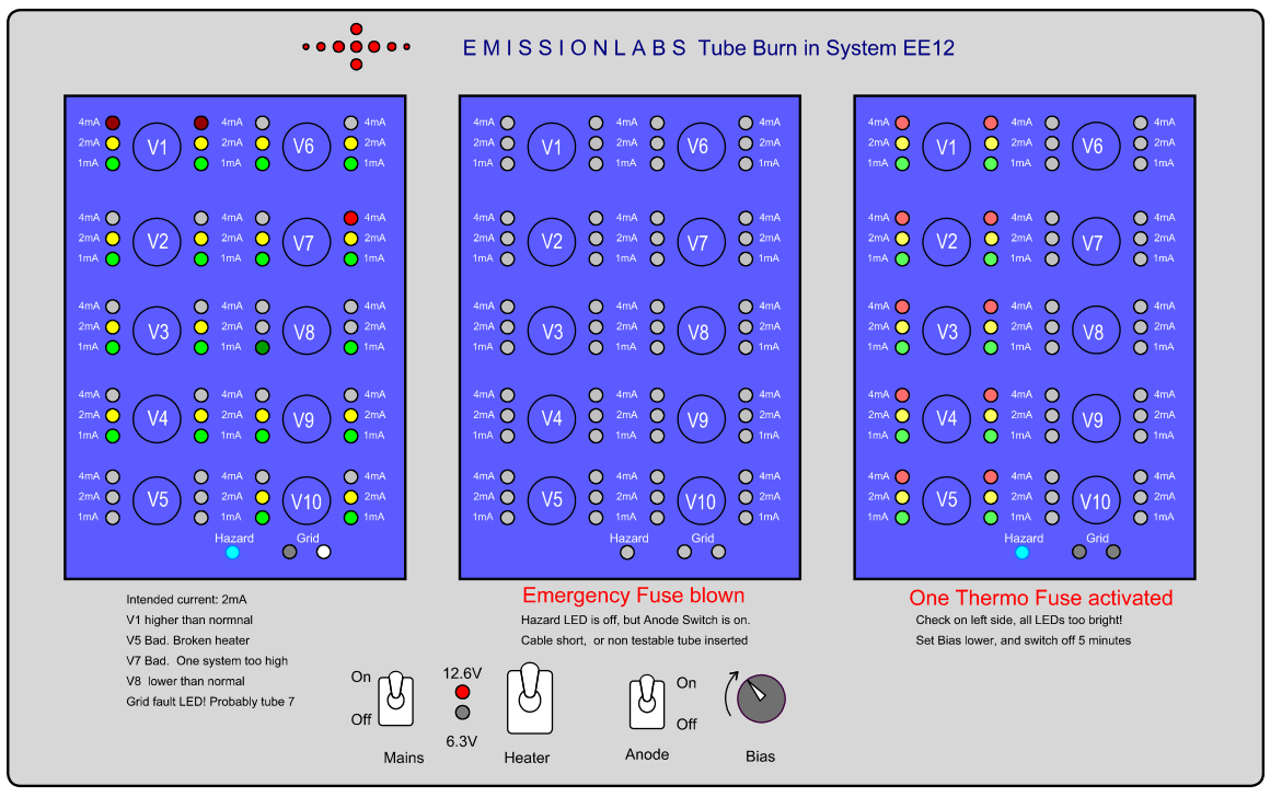
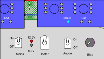 4. Anode On. Hazard LEDs must be on. (One for each board). Since Bias is at zero, there should be no tube current. If yes, such a tube is defective and should be removed.
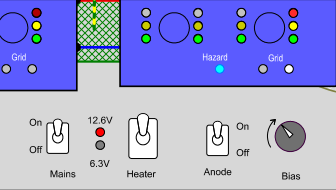 5. Now slowly increase the bias, and watch for faulty tubes. In this example the tube on the right has one defective triode. It draws a lot more plate current than the others. So the left segment is at 1mA (Green) and the right at 4mA (Red). Such a difference of 4:1 is not Normal, and also the grid fault LED is burning. This tube seems defective and should be removed. If there is a grid fault LED burning, remove the tubes one by one, until you find the one(s) causing it. After this pre-testing is done, increase the bias to the desired level, and burn in can begin.
Some fault situations: