Electron Engine ™
Printed Circuit Boards by Emissionlabs
- Tube Test System EE12. Introduction
 Stand alone System, together with Power Supply EE11 (You are here)
- Tube Data Table
- Use EE12 with an existing tube tester (instead of Power Supply EE11).
- Typical Test sequence
- About the purpose of burn in.
- Fusing of the boards.
- Building instructions
- Options and Support
Stand Alone configuration. Power Supply EE11 with Socket Board EE12.
We sell this product is a kit. We supply the bare PCB and the parts.
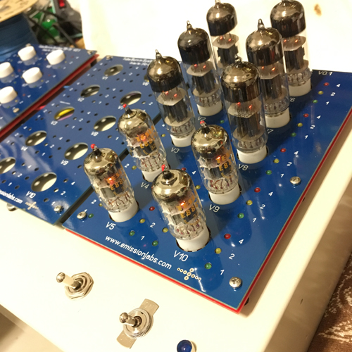
First version 0.1 Boards. Actual Version Boards have the grid current indicator, and "Anode Voltage on" indicator build in.
This a MODULAR TUBE BURN IN SYSTEM. One Power Supply EE11 can be combined with up to three EE12 Socket boards.
The minimum number of tubes to burn in, is TWO 6.3V tubes, or ONE 12.6V tube. The maximum number is tubes is limited by the heater power, which is very high for some Russian tubes, some need 0.75 Ampere, and even though the power supply can do 10.8 Ampere, this will not be able to supply 30 of those simultaneously. Yet for most regular tubes, like ECC81, 12AX7, 12AY7 and many more, the full number of 30 tubes is possible.
The EE12 Tube Test System can burn in, and observe plate current for up to 30 dual tubes, while looking at all 60 tube sections simultaneously, by means of LED indicators. So we have 180 LEDS as current indicators, in steps of 1, 2, 4mA.
Power Supply EE11 Specifications.
- Maximum Plate Current 450mA at 240V.
- Maximum Heater Current: 12,6V 5.4A, or 6.3V 10.8A
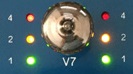
- In case of 6.3V tubes, always TWO identical tubes must be used in each row. So in socket V1+V6 must be two tubes. Then if a tube is placed in socket V2, also a tube must be placed in socket V7, etc, so each time two tubes in a row.
- 12.6V tubes can be placed anywhere.
Cathode cleaning of unused tubes.
During storage, gas residue attaches to cathode. It is advised to let such tubes run at first 30 minutes without anode voltage. This initially removes a part of the contamination, also called cathode poison. Too long stand-by time however should be avoided if tubes are not specified for stand-by operation.
Where to find tube data
For this important information, do not go by talk in the internet, but go by the manufacturer Data Sheet ONLY, and nothing else. Just to give a example, we advise NOS tubes, of specified for stand by operation, to pre heat them with heater only first, for several hours. Telefunken ECC803S is qualified for stand by operation (So heater on, but anode voltage off). Same es the American (less tight specied...6201). But new made Russian Tung-Sol ECC803S is definitely is not. That is because the Tung Sol is only a low grade y 12AX7 with ECC803S blatantly stamped on it. Just the golden letters do not make a wolf from a sheep. If you pre heat those longer than 30 minutes, you will do more bad than good. So read the data sheets, because we can not do this for you. So you want to pre-heat Tung-Sol ECC803S for 24hours, this is not a good idea! You can ask on 5 forums and get 10 answers, but read the Tung-Sol ECC803S data sheet, and you get only answer: That information is missing, the subject ignored. So it not specified, that's what it is. So, this is not possible to do.
General instructions.
- hot swapping the tubes is not possible, this can cause tube damage.
- Tubes may always suddenly develop a failure. For this reason the EE12 may not be used unattended.
- At an over-current situation, the thermo fuses will activate. These will only reset if the tester is switched off, and cooled down. Try no to use these, as they are only intended at emergency devices, and their current is higher as intended for normal use. They activate at 80mA for a column of five tubes.
- Stop any burn in process which develops bad. Do not interrupt it, when it develops good.
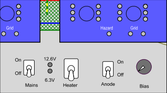 This case must be build by yourself, and you can place the switches any way like it of course. The recommendation is like in this picture, because then before testing, the switches are all downwards, and you flip them upwards one after the other, ending on the right side, with the bias control.
Step 1. Preparations. All switches down, as shown above, and insert the tubes. Look at the test data below here, what tubes can be tested and what is the bias setting.
Step 2. Pre heating. This is very beneficial for good burn in. The pre heating time however is specified in no literature. When you are in a hurry, you might reduce it to 10 minutes, but one hour is better. Some special tubes (with so called double heater isolation), are specified by the data sheet, for longer stand by operation. Such tubes can be pre heated for half a day.
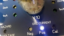 Step 3. Pre Testing. First time anode with voltage on. The blue Hazard LED will now burn. At this moment, bias knob is still set at zero. So there will be no anode current. Still some tubes may show grid current, but this is not a tube fault at this moment, but only some emission leaves the tube via the grid, since the grid acts as a diode at this moment. This is just as in the picture. You can see there, the 1mA LEDs are off, and yet there is some grid current. Increase the bias setting a little bit, and the grid fault LEDs will go off, without any anode current flowing. This condition is good, and the tubes are now what is called, cut off. So all LEDs are off, and only the blue Hazard LED is on.
 Step 4. Anode Voltage on. Anode current flows. Increase the bias, until the green LEDs burn. This is possible for all tubes, because it is only 1mA per triode. The grid LEDs should be off now. It should be possible to set all tubes to zero anode current. Already at this moment, some tubes may draw your attention, when they fail to regulate the anode current in the same way as the other tubes do.
 What to look for? It is the power of this device, the tubes must react all the same, at all bias settings. We get automatically presented the average behavior of the lot. It is really interesting to change the bias, and observe how all tubes react the same, or which have a problem with that. Some will be better than others, but before burn in is finished, we should not judge the tubes yet. Any difficulties may go away, which is ideal, and why we do this. But also, any difficulties may also appear for the first time after some burn in, when the tube were never burned in by the manufacturer anyway.
Now slowly increase the bias to the settings of the table. This should be normally possible for all tubes, and they must behave all the same. Also here, if a tube is totally off, remove it from the test, and find our what is wrong with it first.
It can be observed, initial burn in can sometimes go fast with some tubes, while some others just need longer, but in the end develop good still. This does require anode heat, combined with effective DC current in the mA range. Soon you will have an initial impression of the lot quality.
Please note the following: Bulk packed NOS tubes, today in most cased have been picked from by previous owners. Chances you have such on your bench are high. The same is with re-branded, re-stamped, re-packed tubes, sold as so called NOS. That is a totally different situation, when REAL NOS lot comes out of a sealed 100pcs factory master carton. You will quickly see the difference. It is no coincidence that sealed boxes of 100pcs, test always excellent, but opened bulb packs of 100 pcs always test a bit flaky. Also, new production is generally much less quality, and these are generally not burned in at all. This means some tubes of the lot will develop good, and some will not, and we can now pick out the good ones after burn in.
Step 5, Burn in.
- If there are no faulty tubes, the burn in can begin
- Increase the bias to the level of the table below here
- Now with 10 tubes per Socket Board EE12 this is a total of 60 LEDs per board, and any irregularities will catch your attention quickly. Change the bias somewhat up and down for this.
- After longer time, tubes will become more uniform
- The burn in ends, when there is no more change for a period of 2 hours. The required burn in time is extremely variable. NOS Telefunken are usually good after just hours, but tubes which are not factory burned in, may need 5...50 hours or even more. As long as the tubes improve, continue.
- NOS E88CC (6922) is a very difficult tube. Most, NOS stocks, have been heavily picked from by the many previous owners. Moreover new made tubes or generally not factory burned in. (Read also here)
Step 6, When burn in is finished. Finding the balanced tubes.
Change bias up and down somewhat, and tubes which are not like the others can be detected as 'unbalanced' immediately. Please note, manufacturers did not generally build "balanced" tubes. Any unbalanced tubes were sold just normally, and are considered good. Some very specific tubes however were build "balanced" for special use. The one and only source for this informations is the tube DATA SHEET. Use no other information source, and believe no fake stories when you have access to the data sheet. If balancing is not mentioned in the data sheet, for sure balanced and unbalanced tubes will come out of the boxes. From the ones that are balanced, good pairs pairs can be found easily with a tube tester, and this burn in process has become a major time saver. This was the reason we developed this unit, for our own use.
WIth some practice, and not promised here as a guaranteed way, it is however possible to find quickly pairs which behave balanced and identical after burn in. Just there are no test parameters. When I put such on a parametric tube tester, these appeared always very nice pairs.
How to ESTIMATE the Anode Current:
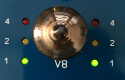
| 0.2mA first beginning of green light | |||
| Green LED burns normal 1mA | |||
| Yellow LED begins to burn 2mA | |||
| Red LED begins to burn at 4mA | |||
| Above 4mA, the RED LED becomes much brighter than than others. This must be avoided. At some point the thermo fuse will activate. | |||
I will add pictures of the burning LEDs later, to replace this table. |
|||
Optional GRID Current measurement during test
The white grid current LEDs on the Socket Board EE12 have a limiter, so they burn only above 1mA. These LEDs are not intended to actually measure grid current, but only to indicate a fault condition. (Adjustable, at minimum 500uA, recommended to calibrate at 1mA)
Power Supply Board Ma and Mb connections
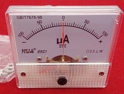 To indicate grid current by itself, some options exist. For this, the power supply board has the connections "Ma" and "Mb", to connect an analog uA meter. This is not essential for burning in, but it may be interesting to check it. This is explained under "Options"
Notes