Electron Engine ™
Printed Circuit Boards by Emissionlabs
- Tube Test System EE12. Introduction
- Stand alone System, together with Power Supply EE11
- Tube Data Table
- Use EE12 with an existing tube tester (instead of Power Supply EE11).
- Typical Test sequence
- About the purpose of burn in.
- Fusing of the boards.
- Building instructions
 Options (You are here)
Options
These are just some ideas about things which would be possible.
- Using a Fan
In case the housing has not enough ventilation, connect a 230V or 115V AC fan (depending on your mains voltage) to the M1 and M2 inputs of the power supply board. - Negative Voltage Output.
Power Supply EE11 V2.3 has the option to generate a negative voltage, unstabilized, or stabilized with a Zener diode. At this moment, we have no plans to use it, but there was room on the PCB. So you never know what ideas will come up later, and PCB tracks are for free anyway. These are parts are not used now, and they are only an empty space on the PC board. The Zener diode is marked D9, the capacitor is C1 and the series resistor is R4. This would be really only a voltage source, of maximum a few mA.
- Using an internal mA meter for grid current.
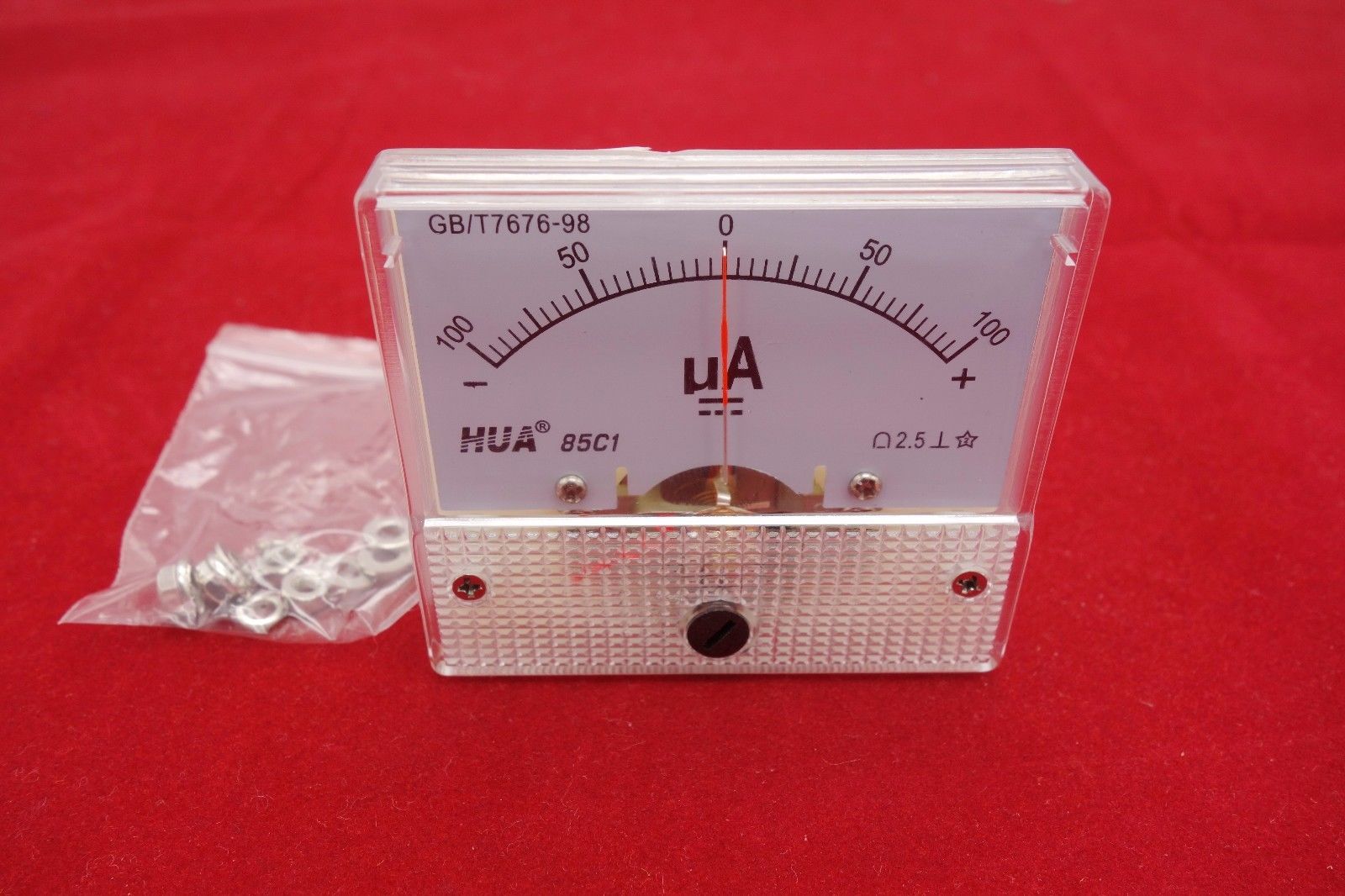
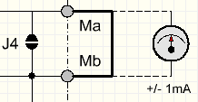 The grid current of each separate Socket Board EE12 is monitored with two white LEDs build in. These burn only if the threshold of +1mA or -1mA for the total board is exceeded. So this is not a current indicator as such, but only "grid fault" indicator. (so a short or leakage above 1mA). In case you are interested in measuring real grid current, starting at zero, connections for an analog mA meter are prepared on the power supply board. They are called "Ma" and "Mb". By default this link is closed with jumper J4, or just by a wire link between MA and MB. So when using an ampere meter, remove the wire link or open J4. Current range of the meter should be appr 0.5 ...1mA, and it should be a version for positive and negative current. Use only an analog meter, and it must be installed inside the tube tester e housing. So there will be no risk on RF oscillation due to long wiring, or strange effects due to digital meters which have unknown electronics build in, which may introduce complications.
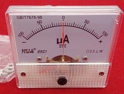
Such a meter like this is needed, or search for this Item number in Ebay:172934983437. Though Ebay part numbers will change quickly. - Measuring plate current of one Socket Board EE12.
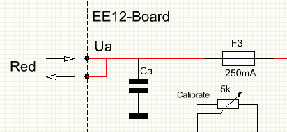
This is also really easy to install. Just insert an analog 100mA meter in the Anode voltage, "Ua" wire from the power supply board to the Socket Board EE12. Use only an analog meter, installed internally in the housing. So there will be no risk on RF oscillation due to long wiring, or strange effects due to digital meters which have unknown electronics build in, which may introduce complications. - Heating with DC.
 In case you want to use a DC voltage like with a DC module, it must be a FLOATING power supply.
Do NOT use a grounded power supply.
In case you want to use a DC voltage like with a DC module, it must be a FLOATING power supply.
Do NOT use a grounded power supply.
The DC module should be 12.6 Volts, and it will be used for for 6.3V and 12.6.V tubes. The switching for this, is done by the power supply board.
H+ is the positive input, H- negative. If you wire it reversed by mistake, there will be no damage, but the tube heater LEDs for 6.3V and 12.6V will not burn right. The DC module should be build into the housing and shielded. This is to prevent RF oscillation, which may be caused otherwise by external cables, acting as antennas.