Welcome to Steve's Vacuum Tube Related Web Site
Note... This site is updated periodically. Current Update Sept 7, 2004. I've modified the "no C" phono preamp. Changed the output stage to a 7721/D3A. Link is from the preamp section below. Previous Update July 31, 2004. I've added technical information on an experimental "no C" RIAA phono preamp. This implements RIAA compensation using inductors and resistors only. There are no capacitors anywhere in the direct signal path. Link is from preamp section below. Previous Update Jan 15 2004. I've added the report on the 7695 Matrix amp that was demo'ed at ETF2003. Updated description in theory section. Matrix is in the table below. Previous Update Jan-02-2004. As promised, I've added Matrix Amplifier information. This update adds reports for the KT88 version of the Matrix amp and for the 813 version of the Matrix amp. There's now a description of each of the amps in the theory section. Matrix is in the table below. Previous Update 12-30-03. Finally, at long last, I've added the variable AC portion to the Owen's inductance bridge. Follow the link in the table below (test equipment section). Coming attractions... the Matrix revisited (reloaded?) Please note that all material and schematics on these pages are (c) Copyright 1997-2004 Steve Bench. All rights reserved. The curves of equal loudness presented on these pages is not my work, rather it was screen scraped from the Radiotron Designers Handbook CD (Old Colony) from Langford-Smith's book based on Fletcher and Munson's work. You are free to use the schematics and info to build your own tube gear. You may NOT build from the information on these pages for commercial profit without having a royalty agreement in place with the author. Feel free to put these schematics or other information on your web sites, but give the author credit. About Me (Highlights of Steve Bench's career so far.)
Note: All Vacuum Tube equipment uses high voltages and is dangerous to work around. The author is not responsible for any "problems", bodily or property, resulting from use of information, schematics or anything else contained on these pages.
The following Categories apply for info and schematics (Click on the box you want to find):
Battery Powered Tube Amplifiers This section contains schematics and description of all battery powered tube amplifiers. The couple watter uses PP or PPP 6AK6 output stage and includes a switching supply to upconvert 12 volts to about 170V. Schematic of a one tube amp using (only) 2 AA batteries. An LC Based Tone Stack:Bass, Mid and Treble. Minimal interaction between the controls. Also illustrates the use of subminature battery operated tubes. The mid control includes a switch to select between 440Hz and 262Hz center frequency. Click Here.
This is a 3 pole tube electronic crossover. The Info file contains data to allow you to tailor it to your desired crossover frequency. Circuit values for various frequencies are contained in the Crossover information file, and the schematic is in the Schematic file. Gary Kaufman [http://www.the-planet.org] has created a small PC board for the crossover. See him for details on availability and costs. Crossover Info
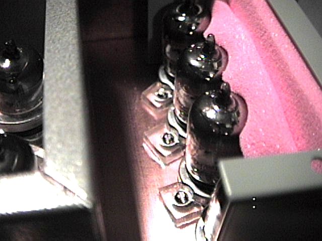
Low level stages often encounter vacuum tube microphonic effects. The read me file describes some ways to avoid this problem. The two "views" are pictures that support the text.
Microphonics Info
A small power amplifier is shown in the battery powered tube amplifier section. An all 417A/5842 power amplifier is shown in this section. It features VERY good damping factor as it is a cathode follower output stage, providing 10 watts using 15 - 417A/5842 tubes. The description, schematic and photo of the breadboarded amp are shown. I have also included a E34L (or EL34 or 6CA7) push pull triode connected power amplifier. This one produces about 16.5 watts at clip, has good damping (1.5 ohms output impedance on the 8 ohm output) and good distortion characteristics (0.3% at 15 watts). It is somewhat a minimalist design, using a 6SL7 and 2 E34Ls per channel. The SE OTL utilizes 10 5687 in inverted mode operation. That report is in the theory section. Also in this section is a truly unique series of amplifiers. They contains only tubes, transformers and inductors. That is, there are no resistors, no capacitors, no batteries, no solid state devices etc. (Including the power supply). In fact, the ONLY parts in these amplifiers and supplies are tubes, transformers and inductors (and chassis, connectors and wire).
Also in this section is another small (300cu in), light (less than 10 pounds), stereo power amp, producing 3.5W per channel. It uses toroidal power transformers as audio transformers and has excellent frequency response. This provides the opportunity to make a very inexpensive amp, and still get good results. Read about it here. Also using these toroid transformers is an even smaller, lighter, but more powerful amp. See the Matrix amp section below.
Another unusual amplifier type is the Matrix Amplifier. I have constructed several of them. They are unusual enough that I've devoted some space in the Theory section to them. Go there by clicking here.
ReadMe Power Amp Info 845 SE Power Amp:
The 841 amp shown here is really a nice amp. Highly recommended.... There are a number of advantages as well as disadvantages to running a tube with positive grid bias (A2, AB2, B2, C2 operation). I explored some of the issues in this series of articles:
There are a number of power supplies available in this section. These can be used for your favorite project, or can be used in conjunction with the designs shown on these pages. The ReadMe covers the schematics in more detail. The text LVPS.txt covers the 12 volt to HT voltage converter used in the battery amp described above. The 2050_Zener text file describes how to use a 2050 thyratron as a 12 volt "zener diode".
ReadMe Power Supply Info The LVPS converts 12VDC (8 D Cells) into 160-170V at up to about 80 mA. 12 volt to 250, 300 or 350 volts, at 40 to 100 watts. Specs and Description This supply is appropriate for a higher power car stereo, or for "car battery" powered systems. It is fairly inexpensive to build, and uses inductors only. Special switching transformers are not needed. Supply 1 provides 150VDC at 30 mA, and 6.2VDC at 0.6A Supply 2 provides an adjustable voltage from 80-180VDC at about 40 mA, and 6.2VDC at 0.6A. Supply 3 provides 300VDC at 100 mA and170V at 80mA and both 6 and 12 volts for heaters. Supply 4 provides 450 volts at 170 ma, regulated 370 volts at 25 mA, regulated 310 volts at 5 mA, 6.3V DC at 1.5A referenced to 150VDC, 6.3VAC at 6A, and regulated negative 56V for bias. Intended to run power amplifiers. Supply 5 Part 1 Supply 5 Part 2 Supply 5 Part 3 Supply 5 was created for the voltage regulator primer. See the Voltage regulator primer table below for details. 845 Power Supply provides independently adjustable and regulated HT supply for 845 or 811 amplifiers. Outputs are 850 to 1000 volts at 100mA per channel, -320 volts regulated bias supply, 2 variable 40 to 120 volt low current sources, 6.3VAC at 2A, and 2 isolated 10VAC 4A sources. For 811-3 or -10, change the 10V transformers to 6.3V. Here is schematic info for voltage doublers to sextuplers:
Tube based voltage regulators. Here's a primer on vacuum tube based voltage regulators:
Note that in part 3 of the above there is a fully worked out variable voltage regulated power supply. It is capable of providing a regulated output from 50 to 450 volts, with about 250 microvolts of ripple and a regulation good enough so that a change of 0 to 350 mA in the load causes the output voltage to change by only 0.25 volts. Here's a very odd voltage regulated power supply. This supply contains only tubes, transformers and inductors. There are no capacitors, yet the ripple is only 40mV at any load! Read it here. Here's yet another shunt regulated oddity.This supply likewise has only tubes, transformers and inductors. It provides a regulated 840 volts at up to about 100mA, with only about 50mV ripple. Read about it here.
I consider this section as a tutorial of different kinds of topologies you can use. Schematics for both RIAA preamplifiers and Line section of the preamp is presented. Read the ReadMe for more info on some of these circuits.
RIAA1 Schematic (417A based with cathode follower) Speaking of RIAA, what does the RIAA frequency response curve look like? Here it is. ***Revised*** Experimental No capacitor L-R RIAA preamp. This one uses no capacitors in the signal path, uses L-R RIAA compensation, uses a triode with a mu of 140 that I got from AES on sale for 60 cents, uses positive current feedback to lower output resistance and is designed to operate in either US (120V, 60Hz) or 230/240V, 50Hz. Weighs in at 23 pounds for preamp and power supply. Very quiet! Here's the report.
A line stage usually needs to have a gain of only about 10. For those who like "colorful" amps, you can build your line stage from a 1629 Magic Eye Tube. These have relatively low distortion, combined with a stage gain of 15 and an output resistance of about 5k ohms. The distortion characteristics are shown here and a simple schematic using the 1629 as a line amp is also provided. Interestingly enough, these tubes have distortion that is almost entirely 2nd order.
A more exotic Line Amplifier Schematic (examples of feedback tone controls, 6SL7 stages, 417A stages, using relays to minimize wiring capacitance, loudness control without tapped potentiometer). The Line Amplifier Description is also available. Also with respect to loudness control: Here's a curve of "Contours of Equal Loudness" , screen scraped from the Radiotron Designers Handbook CD. (excellent reference book). [CD available from Old Colony, curve is after Fletcher and Munson].
I did a "construction project" for the members of "rec.audio.tubes" newsgroup. This was a tube tester that allows you to test a number of different tube types for transconductance and mu, thus providing all the information about the tube. The files in this section are described in the ReadMe file.
ReadMe gm/Mu Tester Info (describes the files below) gmmu1.txt
How do you determine the suitability of an unknown inductor or transformer for your application? Here's a series of articles that will allow you to build either simple or sophisticated inductance bridges. The simplest is a relatively inexpensive but accurate inductance meter. More complex versions described allow you to measure inductance as a function of DC current through the inductor, and/or as a function of AC excitation voltage and frequency.
This was going to be an addition to the RAT gm/Mu tester. Due to the very low level signals involved, I gravitated towards a "stand alone" box. The power section from the gm/Mu tester can be used, or a separate supply as shown in SUPPLY2 in the power supplies section can be used. The theory of operation is covered in NOISE.TXT. This also describes the power supply, tells you how to build and use the noise test instrument and provides a parts list for those interested in building it. The Power Supply schematic is SUPPLY2, the noise testing instrument is NOISEP1.GIF. There are 3 photos showing various constructional aspects of the prototype. They are explained in the text file. The photos are NOISE1.GIF, NOISE2.GIF and NOISE3.GIF. This instrument measures the equivalent input noise of a vacuum tube down to a residual of less than 0.2 microvolts in a 20kHz bandwidth, or with "RIAA" equalized noise. The "flat" bandwidth measures out to be almost exactly 20kHz, the RIAA setting has only 10 dB turnover and rolloff characteristics, but give a strong correlation to what you can expect in a phono preamp. Some results of testing various tube types are available in NOISE4.TXT. RAT Noise Tester Description (noise.txt) It is possible to build up only part of the noise tester. This provides you with a log scale AC voltmeter capable of reading your system's noise level. Read how in the design note below. Noise Tester Design Note: Making a Noise voltmeter. (noise5.txt)
This section covers various electronic and tube related theory items. Don't be frightened, I've tried to keep things understandable. Most of the items here have worked examples included, so you can follow along step by step. LOADLINES For those interested in learning how to "design" an output stage (load lines, operating point, prediction of distortion based on tube characteristics and picked operating point). Part 1 includes formulas for power output and harmonic distortion (second, third, and fourth order) derived directly from the chosen load line. Part 2 provides an interesting view of the question, "Should I pick Rp, 2 Rp or higher load line for my amp?" Part 3 extends the concept into composite curves needed for push pull amplifiers. Part 3 also contains the link to the Excel spreadsheet I used for this series. Part 4 is really a picture show. There are 5 graphs showing a composite load line showing the effects of changing the bias voltage from Class A biasing through Class AB ending in Class B. Part 5 extends the tutorial to pentodes, as there are subtle differences that need to be accounted for when doing a pentode loadline. This five part tutorial contains worked examples.
Following in the same spirit as the loadline series, I've added a zipped Excel spreadsheet (.xls) file that allows you to enter quiescent voltage, current and load. The spreadsheet calculates required grid bias, power output and drive required for either A1 or A2 operation, and provides 3 sets of distortion curves vs power level. This allows you to find "sweet spots" by noting distortion changes as you alter the bias conditions. It's currently set up for an 801A tube (or a 10, which has the same characteristics), but directions are also given for easily altering the spreadsheet to accomodate other devices. Download the zipped file here.
DESIGN YOUR OWN TUBE For those really into designing with tubes (valves), how about designing your own tube? In the past, this was done with a lot of calculations on slide rules, tables, and guesses. However, theory sufficiently detailed to allow successful design did emerge; it was just very "painful". Now, with the help of a little Excel spreadsheet, you can play at inventing your own tube. I have included a small zipped up Excel spreadsheet that allows you to enter your own dimensions for your hypothetical tube. The spreadsheet then gives you the approximate parameters (MU, gm, rp) and then provides a set of plate curves associated with that geometry. In addition to inventing your own "dream tube" you can enter dimensions of an existing tube (6SN7, 300B, 845 or whatever), and get a set of nice, clean, large plate curves. If you haven't the dimensions, (who does?), keep altering the parameters until you get a set of curves corresponding to that tube, by comparing it with the curves you do have. Although it is particularly set up for DHT devices, you can also use it for IHTs. I was able to duplicate 6SN7 curves using several different geometries. (Explains 6SN7 with several plate structures as well as 6CG7). For IHT, use a large number of closely spaced filament wires (N large, and D small in the program). The zipped file is available here. The spreadsheet models normal operation, and includes effect of mu falloff at high voltage and low current, and also models the effects of the grid wire supports.
There is more than one way to make a stereo amp. One old forgotten method lives again. An unusual amplifier: The Matrix amp. My first amp using this technique used YL1060 dual tetrode as a single tube stereo amp. (See table below). The general characteristics of the Matrix amp are discussed in that accompanying article. It is good to review that article first. The Matrix amp has a number of interesting characteristics. It is single ended (2 tubes for stereo) but sounds much more powerful than its measured output. It tends to produce MORE power when both channels are driven. It does NOT like speakers with high order crossovers. I presented a talk on Matrix amplifiers at the 2003 European Triode Festival. In the table below the "link" column gets you to the article associated with that particular version amplifier.
DHTs and HUM DHT's are interesting devices, but the lack of a heater - cathode structure means there is some additional hum issues associated with these devices. There are ways to get 20 -30 dB improvement in the hum level of DHTs while still powering the filament from the line with AC. I've also added the details for cathode biased arrangements. DHT Hum Reduction. Another way of achieving this is to use a PLL to lock to line, and individually adjust time slices of the wave. This provides a way of avoiding any phasing issues altogether. I used this in the 845 power amp describes in the power amplifier section. Here's the report on the PLL Based Hum Cancellation Circuit.
Inverted Triodes Are there alternative ways to hook up a Vacuum Tube? Here's a report on Inverted Tube Operation. It provides an explanation of the characteristics achieved, types of devices that work well in this mode of operation, and the resulting benefits. A fully described output transformerless single ended zero feedback design with good damping is included. I've also investigated the 6AS7/6080 family for inverted operation. Since tubes are not normally "characterized" for inverted mode operation, the characteristics are not necessarily uniform from manufacturing style to manufacturing style. I've found that there are 3 distinct "type" of characteristics found on the 6AS7/6080 family. That report is also linked below. I am also using that principle to test several other principles, such as how to control the hum of a DHT stage, a higher power SE OTL amp etc. It's the "inverted test amp" link below.
Speaking of alternative ways of hooking up a vacuum tube, the pentode can be hooked up in a number of ways. Here's a little report showing the effective plate characteristics of a medium power pentode (6888) connected as a pentode, as a triode, and driven from G3 instead of G1. Pentode Connections.
Also speaking of hook ups, are there alternative ways of coupling your output tube to the output transformer? In this report, I have listed 5 output connection topologies: transformer coupling, parafeed, resistor coupling capacitively coupled to the output transformer, tube based constant current source load capacitively coupled to the transformer and solid state constant current source load capacitively coupled to the output transformer. Here's the report.
One common way of biasing an amplifier is the use of a cathode resistor, and often bypassed with a capacitor. Here's a report describing another method: using a common diode as the biasing device. Diode Biasing. If you decide to try biasing your tubes using diodes, I have built a small Excel Spreadsheet that can be used to find the voltage given current or current given the voltage for a number of different devices. It has several common diode devices built in, and instructions on how to set things up for other diodes. Diode Spreadsheet.
Do capacitors have a sound of there own? Here's a report on the characteristics of different capacitor types in:
Poles and Zeros For those who want some additional theory behind what they're building: Here's a report that walks you thru frequency response analysis using poles and zeros. The example of this technique in "part 1" below goes through an RIAA equalization step by step. The Example in "part 3" below goes through a "Loudness Compensation" technique.
Transformer Frequency Response Model (fb_faq3.txt) What do you need to specify in a transformer. Analyzing an Amplifier (fb_faq4.txt) This covers how to predict circuit gain and frequency response of your circuit. Analysis of the Williamson Amplifier (fb_faq7.txt) This walks you thru an analysis of a common amplifier, covering frequency response and stability issues. For those just learning to use an oscilloscope to monitor their amplifier performance, I've prepared a short visual tutorial on how different types of distortion look like on the scope. View it here.
Tube Related Miscellaneous Items This is my "miscellaneous" section, covering various items of interest, such as how tubes age, differences between brands of tubes, distortion characteristics related to tube type and topology, lifetime information for tubes, "guts" of a tube and related tube info. The ReadMe file has the details for many of the items on this section. ReadMe Miscellaneous Topics Info Confused about the performance of various gain stages? Here's a comparison of several popular topologies. Distortion data for these topologies is shown. Description of several topologies and their resulting distortion characteristics (testsch.txt) Schematics of above (testsch.gif) Speaking of different topologies, here's a small Excel spreadsheet you can use to calculate the gain of a cascode amplifier stage. Also embedded is a calculator that will calculate Rp given MU and gm, and calculate MU given gm and Rp. Cascode Stage gain calculator. I've added a page graphing distortion components of a 12AX7 set of amplifiers, covering a standard amplifier, one with unbypassed cathode, and the equivalents with paralleling both sections of the tube. There have been some indications that doing this doesn't sound as good. The results of the distortion component tests are quite revealing. 12AX7 stages- Distortion components vs level Along the same lines, is there a real difference between operating low level(line level) stages with battery bias vs operating the stage with a bypassed cathode resistor, there a comparison between 12AX7LPS (the "new" "long plate" 12AX7's) operated under both conditions: Batt. vs Cath. Bias. Ever wonder if a normal vacuum tube can be operated successfully at low plate voltage? Here's a set of tube curves for a 6SN7 at low plate voltages. 6SN7 at low volts If you don't like 12AX7's, how about using a 1629 Magic Eye tube as your line stage. The resulting distortion characteristics can be viewed at: 1629 Magic Eye as amp. This tube will produce a gain of 15 with an output impedance of only about 5k ohm. There's a more traditional use of the 1629 as a magic eye in my report on Amveco toroid transformers shown here. I reported an interesting effect that happens predominantly with directly heated triodes. As the filament voltage is reduced, the distortion produced by the stage drops dramatically. Data is presented for 01A, 1619, 26, 6B4, 1U4 as a representative sample of different DHT types. All share this effect. I have uncovered what is happening, by examining the characteristic curves of an 01A with normal filament (5v) and starved operation (3.2v). Direct heated triodes with starved filaments
A popular question: How long can you expect tubes to last? Here's data from MIL-217 "reliability" data. MIL-217 Life Predictions for Vacuum Tubes (tubelife.txt) Ever wonder how much current a vacuum tube can really take before lifetime is impaired? Here's a short report on predicting that current based on the heating power. It covers thoriated-tungsten filament types, directly heated coated filament types and indirectly heated heater-cathode types. It is interesting to note that the best efficiency in terms of current per watt of heating power is obtained with directly heated coated filaments. (The 300B and 2A3 fit this category). Here's the report. Wonder what's inside that metal Vacuum tube you can't see into? I should also note, after working with tube parts (disassembled) it's a really good idea to wash your hands. 6SJ7 Cutaway: View 1 - View 2 - View 3 - View 4 For those with limited test equipment, here's a poor man's distortion analyzer. (Sorry it uses 1 transistor). ---Return to Category Selection---
By the way, to get in touch with me, you have to remove the "one zero one" from sbench101@aol.com. Sorry for the inconvenience, but the SpamBots, you know. I do welcome questions and comments. -Steve |
|---|