So far, we have discussed what poles and zeros do to alter the frequency response. In this article, we will see how some interesting characteristics can be utilized to make a "compensated volume control" commonly called a "loudness" control. This is based upon work originated by Fletcher and Munson. As the sound level decreases, the ear becomes less sensitive to both extreme low and high frequencies. Thus, when listening at reduced levels, if the frequency response of your system is maintained flat, you will not hear those extremes as well. Loudness compensation is used as an attempt to restore these frequency extremes. This comes and goes in "favor": the current "high end" amplifiers choose to eliminate this control.
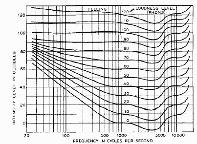
Here is a curve of "contours of equal loudness". This was screen scraped from the Radiotron Designers Handbook CD which was a re-issue of Langford-Smith's book (which I believe are both available from Old Colony Sound).
.
There are some interesting items to note in this curve. The low frequency "pole" shifts upward as the level is reduced, and the actual high frequency compensation "slope" is quite high, changing about 15dB from 4kHz to 15kHz (which corresponds to about 2 "zeros" of real compensation). Many "loudness compensation" schemes provide a "fixed pole-zero" on the low frequency end, and some ignore the high frequency compensation altogether.
We will discuss a compensation mechanism that addresses both of the issues raised above.
We will limit compensation to lower levels only, placing the compensation network "around" the volume control. This will provide a "flat" response at zero attenuation (presumably at very loud levels) with increasing compensation at lower levels. Some other limitations we will self-impose: must be switchable, with at most a double pole switch per channel (4 pole for stereo). Compensation will be continuous with the volume control.
Bass
Recall the RIAA portion of this series. A low frequency pole-zero pair is implemented with a series resistance from input to output then a series resistor capacitor to ground. But this is precisely what you get if you put a capacitor in series with the "ground" lead of the volume control. Moreover, as you "lower the volume", the resistance in the ground side is lowered, raising the zero. This has the effect of sliding the compensation point higher in frequency as the overall attenuation is increased. By inspection of the contours of equal loudness above, this is what is required. For instance, the compensation at "90 dB" causes a bass boost starting at about 20Hz. At "70 dB" this has increased to 150Hz, At "40 dB" it has increased to about 400Hz. It would appear that we have all the compensation capability we require. (You WILL note that we would truely need to make a multiple pole network to accurately compensate, but this provides a reasonable compensation with minimal fuss. About the only thing we need is to place a small series resistor in the ground lead to prevent the zero from getting too high in frequency near maximum attenuation.
For a 500k pot, typical of volume controls, a 100nF in series with a 330 ohm resistor in the ground leg will operate nicely, as we will show later.
Treble
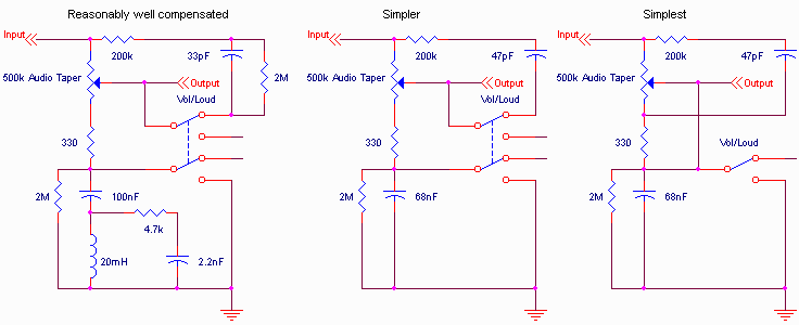
This is a little trickier, since the high frequency response has some "wobbles" in it. I'll get into the theory of complex poles and zeros that create these wobbles in another part to this series, but for now, simply state that an L-R-C circuit can be used to create this. In fact, a series L-C circuit creates a low impedance at resonance, and a parallel L-C circuit creates a high impedance at resonance. So, if we place a small inductor (20mH) in series with the (presumed) 100nF capacitor, we can achieve a low Q series resonance in the 3-5kHz range as shown in the curves. Then if we place a small series resistor capacitor across the choke (say about 2nF) we can get a relatively low Q high impedance above 20kHz, providing some treble boost, as required. If we accompany this with a small capacitor in series with a resistor from "input" to "output" we have easily achieved the multi-pole response needed, without too much complication.
The Circuit
Here's what the overall circuit will look like:

Note that I've given 3 alternative circuits: the leftmost one is the one I've described above, with progressively simpler (and less effective) methods also shown. I've seen even simpler (and ineffective) attempts used that take the circuit at the right, eliminate the 47pF and 200k, eliminate the 2Meg and short the 330 ohm. The 2 meg resistors are used only to eliminate "pops" when the switch is thrown. (These eliminate any charge stored on the capacitors from being heard as a pop when you throw the switch).
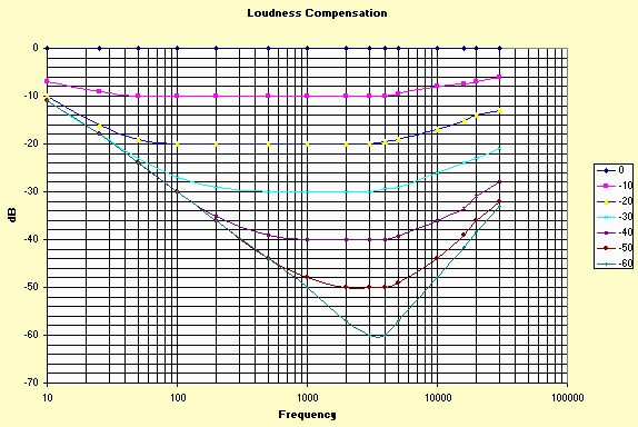
The response associated with the circuit is:

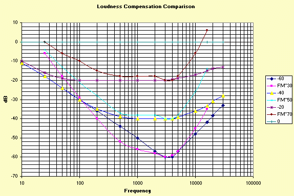
This circuit "undercompensates" loudness, but follows the same general trend. Here's a comparison at 3 selected loudness levels:

One thing to notice is that I've equated the "30" curve with an attenuation of 60dB, and consequently the "50" curve with 40dB attenuation and the "70" curve with 20dB attenuation. In reality, the overall system gain sets the absolute level for any degree of "volume control" attenuation. This is why you sometimes see a "loudness" and a "level" control being two separate controls.
-Steve