Part 4: The Effect of Bias Change on Composite Loadlines - from Class A through Class AB to Class B
There has been some speculation whether there is a large or small difference in the sound quality of a Class A or a Class AB amplifier. This rather short part of our series shows the effects of altering the amplifier bias. For consistency, the same "invented" tube is used.
This first curve is pure Class A, with both tubes drawing current during the entire cycle.
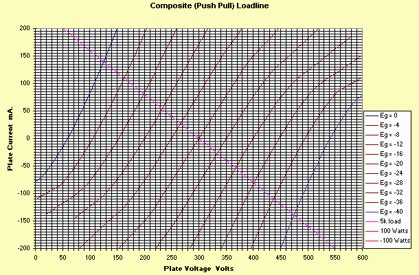
Notice the very constant plate resistance, and very smooth composite set. Very little distortion will be heard, whether the load is resistive (as shown), or very highly reactive (the load line looks like an ellipse instead of a straight line).
This next curve is the limit of pure class A operation. The bias has been increased (the grid biased more negative) so that one tube just reaches zero current as the other one reaches maximum current.
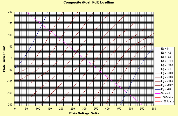
Notice that while the curves are still very straight, a "kink" is starting to become evident as the second tube cuts off.
The third curve is typical Class AB biasing, where the tubes are really operated in Class A for all but the highest power outputs.
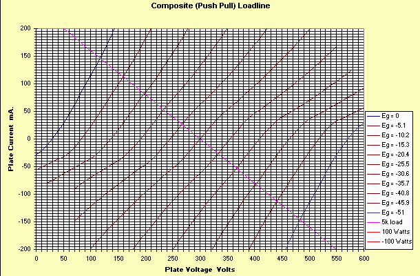
Notice that there is a gradual transition towards sloppiness of the curves. There are three things to note in the Class AB operation:
- The plate resistance is still constant THROUGH the load line.
- For Reactive loads, the load will hit some really variable portions of the plate resistance. This will have audible effects if your speakers are reactive, but probably be unnoticeable on a really "resistive" speaker.
- There is a "common wisdom" that the plate resistance will change in Class AB when one tube turns off, since the plate resistance "changes from two parallel tubes to one, so the resistance doubles". Nonsense. The curves clearly show this does not happen. In fact, the effective plate resistance is slightly lower in those portions where one tube only is conducting.
In this next curve, the bias is increased even further. There is still significant idle current, but the transition to one tube operating occurs at much lower power levels.
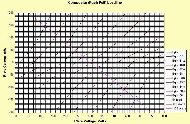
In this curve, you can see fairly clearly the "crossover" region. The gain is definitely lowered for small signals. Some may think this is a form of xpansion. What it is, is a form of really obnoxious distortion. Yet for smaller signals, the amplifier is STILL running class A.
This final curve is just the threshold of Class B. One tube turns OFF just as the other one starts to conduct. This won't sound very good.
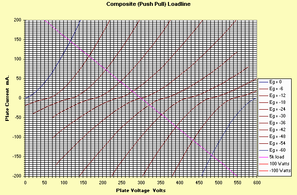
Notice there is no "magic" of the transition from one class of operation to the next, but rather a gradual transition.
By the way, the curves were collected by a "screen scrape" of the Excel Spreadsheet. I've set these up as easily modifiable curves in the spreadsheet. The file has been zipped to download easier. It's at: http://members.aol.com/sbench102/platcurv.zip
Hope you've enjoyed this series.
Steve