Part 2 - Effective Plate Resistance
One of the questions you may hear asked is how to pick an adequate load line for your design. You will hear talk about picking it with respect to the plate resistance of the tube in question.:"Pick the load resistance equal to the plate resistance to maximize power.", "Pick the load resistance equal to twice the plate resistance to maximize power.", "Pick the load resistance higher to minimize distortion.", "If you have a fixed input, the maximum power is ...".
None of that is much help. The biggest problem you have facing you is the load line. This is usually established by the characteristics of the tubes you choose, and available components (output transformers in particular). The bias, high voltage (B+ or HT voltage), and drive are usually determined AFTER you establish an output stage characteristic. Then, if one of those secondary parameters is unrealistic, you "iterate" the output stage characteristics.
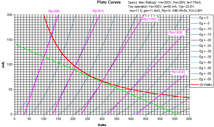
Plate resistance is not constant. It varies widely over the operating load line. We will continue to use the same example as previously... my "invented" triode. In the figure below, I have plotted the tangent line to the operating characteristics we used in the previous article at the same 5 points on the load line we used to calculate distortion.

Notice that in this case, the plate resistance varies from 580 ohms to 2020 ohms. So, if you used the 2x Rp "rule of thumb" (or was that rule of middle finger?), which value do you pick? The 1000 ohms specified by the manufacturer, the 580 ohm minimum, the 1050 ohms at "quiescent", the 2020 ohm maximum, or yet another number?
In our operating example the load line varies from about 2:1 Rl/Rp (at minimum current) to about 7:1 Rl/Rp (at maximum current). AND, this assumes a constant speaker impedance. In reality, most speakers vary an additional 2:1 to 10:1 over their operating range, further complicating things.
So, what do you do? You pick an operating point as described in part 1; one that is within the tubes ratings and produces a reasonably wide operating range. If it fills your needs, you're done. If it doesn't, start over again. Moral of story: don't be particularly concerned with the load lines relationship to the plate resistance. As we've just seen, the plate resistance varies.
Effect of Variable Plate Resistance
You might wonder what the effect of the variable resistance is. This will change the damping on the speaker over the signal range. For instance, let's consider a band limited square wave (one with rounded edges that "fits" within the bandwidth of our amplifier). The speaker might "ring" on the "edges" of this waveform. That's usually why higher "damping factors" are usually considered desireable. In this case, the ringing at the edge associated with the high current point will be damped MORE than the ringing at the edge associated with the low current point. This is a case where the amplifier cannot correct for a speaker defect.
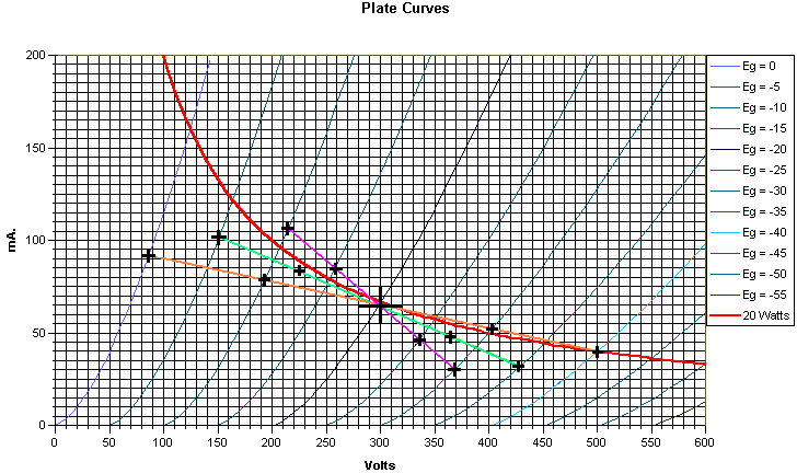
There is another, in some sense, worse effect. Let's further "modify" our hypothetical source by placing a smaller, high frequency sine wave component on top of the square wave. I'll stipulate that this signal's frequency happens to be at a relatively low speaker impedance point. Now what happens. The portion of the sine wave riding on the high current part (lower impedance) will have higher "gain" than that portion riding on the lower current part of the loadline. This is an insidious form of intermodulation distortion that is usually not very musically pleasing. You can somewhat minimize this effect during the establishment of your load line. If you followed the procedure I outlined in part one, go back and re-plot the loadline using HALF the resistance, then TWICE the resistance. Don't be particularly concerned about whether the newly plotted loadlines remain inside the power dissipation characteristics. (Why THAT is, is outside the scope of this particular article). Now calculate the distortion FOR APPROXIMATELY THE SAME power output on these 3 loadlines. Continuing with our example, this is shown below. The original loadline (4k) is green, the 8k loadline is orange, and the 2k loadline is magenta. I've shown the current and voltage points needed by black crosses on the curve.

Notice that the input signal levels for the highest impedance is twice that of the lowest impedance, and the original curve is intermediate between these. The points to pick are limited in two ways: The signal for the highest impedance will usually cause the limit at "0" bias. This fixes the max signal. Sometimes the signal at the lowest impedance reaches cutoff. If that happens, choose a maximum level to remove this restriction, and re-derive the points for the other impedances. Caution: If this happens it is usually an indication that the load line you originally picked is not close to optimum).
Results:
Remember the formulas we used:
Po=(Ve-Va)*(Ve-Va)/(8*RL)
HD2=75*(Ia+Ie-(2*Ic))/(Ia+Ib-Id-Ie)
HD3=50*(Ia-(2*Ib)+(2*Id)-Ie)/(Ia+Ib-Id-Ie)
HD4=25*(Ia-(4*Ib)+(6*Ic)-(4*Id)+Ie)/(Ia+Ib-Id-Ie)
The data points are:
8k: Va=86, Ve=500, Ia=92, Ib=79, Ic=65, Id=53, Ie=40.
4k: Va=150, Ve=427, Ia=101, Ib=82, Ic=65, Id=49, Ie=32
2k: Va=214, Ve=369, Ia=107, Ib=85, Ic=65, Id=46, Ie=30
These lead to the following results:
| Load Z | Pwr Out | HD2(%) | HD3(%) | HD4(%) |
| 2k | 1.5 | 4.5 | -0.4 | 0.6 |
| 4k | 2.4 | 2.2 | 1.4 | -0.3 |
| 8k | 2.6 | 1.9 | 0 | -1.9 |
You can see that the distortion at the lowest impedance is highest, but is comparable at all 3 impedances. If these were wildly different (say 1.5% to 10%), this would be an indication that your amp is likely to sound less than desireable, and it might be wise to choose different operating points.
What else can you do? Feedback is one possibility. I generally have good luck with some slight local feedback from the output stage plate to the driver plate. This does not suffer from a lot of the global feedback effects that shun people away from feedback in general. You are free to go back and start a different set of load lines, to see if you can improve things.
In a later installment, we will see how push-pull operation affects the effective plate resistance.
One additional Clarification
In the example we have been using, the quiescent voltage is 300 volts. In building the power supply for this amp, don't forget to include the voltage drop in the output transformer. If this were, for instance, a 110 ohm winding, the power supply needed would be 307 volts. If this were, in addition, a "self biased circuit" (i.e., bias derived from a cathode resistor), the 20 volts bias would also needed to be included, bringing the power supply required to 327 volts.
Steve