Electron Engine ™
Printed Circuit Boards by Emissionlabs ®
- Tube Test System EE12. Introduction.
- Stand alone System, together with EE11 power supply
- Use EE12 with an existing tube tester (instead of EE11 power supply).
- Typical Test sequence
- Building instructions
 About the purpose of burn in. (You are here)
- Options
About burn in.
In tube production, it comes down to one thing, and that is keeping contamination away from the cathode. In a working tube, such contamination at first will be a positively charged ion in vacuum. As the working anode is positively charged,it pushes such ions away in all directions. Some land on the glass, recombine there with an electron, and in case the ion was not a gas, the resulting molecule will stay on the glass. Over time, the glass gets darker. Some other part will land on cathode, and compromise the emission. Some elememts don't do much damage, such as carbon, but others like Chromium are real emission killers. How to get rid of this? One way is designing the cathode a little bit too hot by default. That will slowly evaporate the contamination, but also wears out the cathode faster. Another process is to add emission enhancers to the Cathode coating. In the powder mixture, some small part of the Barium is always replaced by Aluminum and Strontium, because aluminium is a ideal emission starter of new born tubes, and Strontium generally enhances emission during the rest of the tube life. However that is not just doping it with fractions. In fact this requires so much Aluminum and Strontium, that the Barium content becomes significantly lower. Yet, such tubes work initially better, and even tolerate a lot of contamination. They also have a much shorter formatting period (something like burn in, but not the same). On top of that, they need less burn in, and most of them will keep the desired specifications right from the beginning very well. All of this works very nice. Apart from one thing: There is substantially less Barium in the cathode mixture. However the Barium is the heart and soul of the tube. This is the substance which gets used up by simply using the tube, and there is no other way. Less Barium depot means less life time.
So the production processes target either for long life tubes which are expensive to make, and need a lot of burn in. Or, for low cost tubes, which by definition can never be long life, due to their higher cathode temperature and lower Barium content.
With NOS tubes, these have most of the time cathodes with a very high Barium content, and these need a longer burn in period.
The purpose of burn in.
In short, this brings the new tubes closer to their final specifications. It should be clear, that only after THIS CONDITION was reached, it makes sense to do the matching. Not somewhere half way, and for sure not match tube right out of the factory boxes.
The burn in effect has a tendency to disappear, most of all with low Barium content tubes. Though with such, due to the higher doping, it will restore again faster. This explains the observations of some tube doctors, demonstrating with a white doctor's coat on youtube, how they burn in tubes by over heating them with a normal tube tester. Telling how well this works. But is this really so....? Just do the math. Suppose he burns in 120 tubes, on his tube tester, and lets each tube run only 2 hours. Like this it takes him one day to burn in a quad, and it will take him a full month to do the 120 tubes and get 30 quads. So he will be tempted to compromise on the burn in time, which in this example was low already. And since such tubes burn in relatively fast, it's probably done like he says indeed.
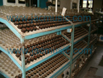 When working with NOS and other more expensive tubes, these have generally a higher Barium content, so less Aluminum and Strontium, and lower cathode temperature. To make this possible, also higher base quality of the materials. Burn in of such tubes takes so much longer, nobody can seriously do this on a normal tube tester. It needs a device which can do many at a time. In the old days of tube production, the factories did 1000's at a time, filling complete factory floors. This picture is from the EI factory
Any burn in process, as used by tube factories, I have seen none documented in literature or elsewhere. This text here is only valid for Barium Oxide Cathodes of after 1940 technology. (Earlier technology used other materials, or even Barium "pill" coating like first AD1 tubes - All of that is not the subject here)
What will burn-in do?
It seems virtually everything which can go wrong with a tube, will be less of a problem after burn in. It improves the cathode, the vacuum, the mica, cleans the metals, activates the getter, and even makes the glass at the inside anti static. Almost anything, you name it, and burn in will do it. The longer a tube was stored, the more it is going to benefit from burn in.
In short, burn-in starts these processes:
- Increase the emission, by evaporating contamination from the cathode surface.
- Make the cathode surface more homogeneous (emission wise), reducing noise.
- Make the tube curves overall better, reducing distortion.
- Clean the grids partially, for more stabile bias.
- Clean the mica, for less sputter or pop noise.
- Loosen too tight connections between mica and metal parts, for less microphonics.
- Improve the vacuum for less noise and closer factory specifications. (See Note3).
- Harsh sound will disappear, this is due to all the above effects together.
Quality and Reliability
This is also what burn in improves. Not just does burn in improve the tube data. Sometimes it does not do so! Some tubes can go down in emission 25% just after 24 hours. If that is good or bad, depends simply if they were too high before burn in. So if plate current was unacceptably high before burn in, you might say, not all of them passed quality testing before burn in. Then, after burn in more tubes will pass, and this is improvement.
However when a lot is just "so so" when you begin, they either improve, or get even worse. In the case they went down further, they are worse as when you started. Is that a burn in failure? No it is not! The same would have happened in an amplifier. However after such burn in, the weak ones are removed from the lot, and the strong ones will (logically) have less failures than the whole lot before burn in.
What will burn-in not do?
1) Burn in, can not make a weak cathode strong, or make a gassy tube be none-gassy. Improvement yes, but defects will stay defects.
2) Burn-in can not remove mechanical tolerance. Anode distance is the largest single mechanical tolerance factor for triodes. With pentodes, it is rather the grid distances, which burn in also can not change.
We need to take some time to understand better the above influences the tube curves. So effectively, the bias point and transconductance. It should be clear, defects or mechanical tolerance can not be removed by burn in. So please read this text carefully, it is not very easy to understand, but you will likely find it nowhere else in the internet. This is collected information from our own tube production in Prague, at the EMISSIONLABS factory.
What happens, has to do with basic principles of negative feedback with signal amplifiers. A tube is an amplifier with the input signal at the grid, and an output signal is found at the anode.
However inside the tube, the "grid voltage" is not directly present as such. It is the grid FIELD which controls the electron flow, and this field is different at every different inside the tube, as it is by definition a spatial effect. So, electrically we have the grid voltage on the grid itself. But at any distance away from the grid, so where we expect the electrical field, to do it's work, the voltage gradually gets less. So at 0.1mm from the grid, the grid field is another, and a 0.2mm etc. All the way long, he grid field will do it's work, sending back electrons to the cathode.
At the same time, there is the anode field which does the same thing, apart from the fact everything is.... REVERSED. So the anode DC field, is positive voltage, and the anode electrical signal, the AC field, is in reverse phase with the grid AC field. So far so good, but take good note, the anode AC field is in reverse phase. Grid field and anode field spatially add up, and what we get is the resulting field.
The above is the mechanism. What may be easier to understand, is what it will do. So via the construction inside the tube, we have effectively some negative feedback of the anode AC signal to the grid AC signal. And because these (spatial... field....) signals add up, this will follow the normal rules of negative feedback theory, because the anode AC field is in reversed phase. The point is now, tubes with a larger anode distance will have less of this feedback than tubes with small anode distance. Having understood this, we can now see how anode distance tolerance will influence the tube data. We must keep DC and AC effects apart. These will behave opposite!
Let's take an example, we have a new, good tube, but it has a small anode distance, due to mechanical tolerance. Such a tube will not last longer or shorter just because of that. This will however cause more influence of the anode field. So anode DC current will be higher at the data sheet grid voltage. Calling such a tube "higher emission" only because plate current is higher, would be an amateur mistake! But without any knowledge of how things relate to each other, this is the most common conclusion, of course. Though it is wrong. We stay with the same tube, so anode distance is smaller. The anode AC signal, is however phase reversed with the grid AC signal. The smaller anode distance will now cause more negative feedback inside the grid, with all the known effects of this. So more feedback causes lower gain, and higher Ri, and the result of this is lower transconductance. So depending on what you look at, DC current or Gm, the tube will be better or worse! As you already expect now, neither is a good conclusion. However, it is 99% of all the babble and misconceptions, what this is about. We stay with the same tube... My observations are, the effect is pretty linear. So when the anode distance is such, that a factory-new tube has 10% more DC current, it will have 10% less Gm. So always put DC current in relation to Gm, and then you are doing it right. If BOTH are lower, THAT is a sign of lower emission. Not just the one, or just the other.
People who look at Gm in an AUTO BIASING circuit however, will see little difference, because the auto bias point a tube takes, is depending of those factors in combination. The good thing is, auto bias result is hardly dependant on anode distance tolerance. So this is the best way to judge tube quality, as it bypasses this issue.
The above is not easy to understand. Just read it a few times, and keep in mind, plain normal feedback theory for amplifiers. All of this applies to tube geometry as well.
Tube manufacturers for that reason will NEVER say you have to test with fixed grid voltage. This would be essentially wrong for the above reasons. They know those, and they never advise to do so. Just check for it! EVERY tube data sheet, which tells you how to verify the tube, will say it has to be done in auto bias. Not by using this word, because auto bias is electronics slang, but by specifying the appropriate test circuit for that, which is as you will see: Auto Bias. And no, you will not find that in the low class, commercial tubes data sheets. For this you need to study the really professional data sheets, like C3g, or D3a, or Telefunken E88CC, ECC803S, and data sheets like that. None of them will ever specify to test plate current at with fixed grid voltage. (Only exception is such very special battery radio tubes, which use the heater voltage also for bias). So when for instance ECC83 is specified with the average data: Ua=250V, Ug=-2V, Ia=1.2mA, Gm=1.6mA/V, that is not saying you must test "must be so" at -2V Grid. So do not dispute this if you want to know more about this, but read the Telefunken ECC803S data sheet for how to test this tube. And you will find the value of..... the AUTO BIAS resistor in there. So, auto bias, that is how it is done.
Conclusion: Burn in will not help to remove effects caused by anode distance tolerance, specially not when you test with fixed grid voltage, which is completely wrong to do anyway.
How is burn-in done?
Actually, there is little historical information available. Keep apart a process called activation, and the process which comes next, called burn in. Activation at first is done with the vacuum pump still attached to the tube. Like this the heater gets glowed for the first time, which sets free a huge amount of CO2 gas. This is normal because the heater coating is a carbonate, which turns into an oxide after the CO2 is set free. Also the binding compound, a little bit something like glue, which keeps the coating attached to the cathode, gets burned, and releases water and CO2. When this gas is pumped out, the tube becomes alive, but no more than that. Now the grid gets cleaned by using it as an anode, so to out glow it. Also the anode gets cleaned by over heating. And when that is done, the whole tube is set under current, for further over heating. When no more gas develops, this process is closed, and the tube is taken off the pump and sealed. Of course all of this was not so nice for the cathode, but when done no more than needed, the cathode survived. Now comes the factory burn in. This will develop a good cathode by using the right electrical conditions, which are actually tough conditions. This will make the good tubes better, and the bad tubes worse. The last is why low cost production sites burn in as short as needed, simply the yield is higher.
A user burn in, is needed after decades of storage, or when factory burn in was too short. This burn in is generally done at lower dissipation, because any form of over-heating or use maximum limits, is often counter productive. This assumes of course the factory burn in was done. So in contrary to a factory burn in, a user burn in will not try to clean the grids by means of grid current, or outgas any other parts of the tube aggressively.
Original factory burn in.
Here you see the original burn-in street of the AVVT Factory in Prague. I made this picture myself in 1999. Light bulbs were commonly used as anode current stabilizer and fuse at the same time. It's not very energy efficient, but it works extremely reliable. Anyone can immediately see if one tube of 100 is not working right. The EE12 burn in unit works similar, but we use LEDs instead of light bulbs. .
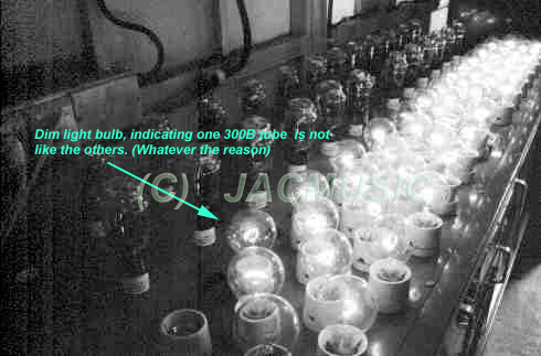
Light bulbs as current limiting devices, in the AVVT tube factory, 1999. One tube is not good. This is exactly how burn in works, as none of those had seen a tube tester yet, and still one tube was already pointed out.
The AVVT factory was closed somewhere in 2001 - Read more about it)
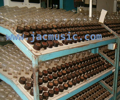
Light bulbs as current limiting devices, in the former EI tube factory.
(EI factory Closed in 2014 - Read more about it)
How to see if burn-in is needed?
When putting several tubes of the same kind in the EE12. it can immediately be seen if they are all uniform or not. Initially there is no need to verify data sheet specifications. Even so, identical behavior finishes a successful burn-in. So when (good) NOS tubes are fired up after 50 years for the first time, you probably will see a bit of a mess, when you expect them to be all the same. This burn-in device already shows this before burn-in. So when inserting 30 dual triodes running in three boards, we have 60 different triodes running, and 180 LEDS to indicate the result. This field of LEDs will now burn uniform for tubes that are successfully burned-in already, or don't need a burn-in. And yes, as tubes dealer, I can tell you this: Such tubes do exist, right out of the 50 years old boxes, it is not unusual. But it is also not unusual., if at first we see a small chaos, and still these are by no means bad tubes at all. They just need a burn-in! I have used four L3-3 testers for this and at least I could burn in 4 tubes at a time. However burning in tubes like that was too tedious.
With the EE12 Board, any unbalance between two triodes in one bulb, can now be seen immediately, because for different plate current, not all colors of LEDs will burn, and the ones that do burn have different brightness. Though all tubes are in an auto bias system, the setting for the auto bias is widely adjustable for all tubes together, but in the SAME way. Non-conforming tubes will immediately catch your attention, by reacting different from the others. It is really the same as in that AVVT test street in the above picture, just now it is miniaturized for small signal tubes.
How to see if burn-in is successful?
Simply when the first tubes begin to improve already after 30 minutes, this is promising for the whole lot. A burn-in process is usually slow, and should not be forced for that reason. Some tubes are fine after a just hours. Some others need days. What counts is the final result, and not how fast it went. Even so, long-life tubes, have a chemical composition which by default will burn-in slow. And by the opposite, such tubes which appear to burn-in faster than other brands, may not be long life tubes by design. (See Note3). So a slow, steady burn-in, is generally the best when you observe this.
Do not force it, and do not interrupt it.
When a burn-in which seems to develop nicely, it should not be interrupted to check if Gm has already improved, or if the tubes sound already better. If re-started after that, it doesn't necessarily have to continue as good as as it was doing before. Well this risk is small, better avoid it. However there are no hard rules. Sometimes an improvement will not take place, and and a short overheating of the heater may start the process, or make it worse. So brute force is generally the last thing to try, and IF that helps, it is often not very permanent. In short: anything that works: let it run. Anything which develops not good: stop it.
When is the burn-in finished?
This is hard to say, but generally this would be when all tubes test more uniform, and more balanced as they were before, and most of all when no more positive change appears. This take 5...50 hours. Most of the time rather 5 hours. Please note, burn-in can only restore the good condition if this is possible, but generally if the tubes were "down" too much from over storage, or the whole lot is not so good, they will not fully recover. Yet a some improvement can be expected, but not if the lot is very much mixed quality. (So if all tubes are totally different). If the tubes are just not good any more to begin with, burning in will probably bring the plate current down further, and using them in an amplifier will result in the same thing.
It can not be said often enough, that the LOT QUALITY is the #1 thing to look at, and not how close a particular tube is to the data sheet average value. Being closest to average was never a quality indicator, and you will not find this written in any data sheet or test hand book. (See Note4)
Conclusion:
Hard core audiophiles love contrary opinions, so my best bet is to agree with them, and drink a beer on it :)
Notes
- A cold getter during storage will maintain vacuum not really, and for sure will not absorb contamination.
- A bad method, it is to bake the whole tube passively in an oven, but some bad sellers are doing this. Burn in will be partially only, but most of all, this causes an increase of vacuum problems later. This can and will cause micro cracks along the tube pins, after some 500...1000 hours of use, with some 5% of the tubes. This number is estimated, depends on many variables, but you have to see it is not zero. With good NOS tubes you can expect 1% bad vacuum tubes after 50 years of storage, and the other 99% are simply good. This is normal. But when new made tubes come out of a 100 pack with already too low emission, and then during storage they get worse, something is suspicious.
- Even more difficult to see, these micro leaks are initially only visible as slightly
 lower emission only, and not visible as vacuum loss at first. So users think it is normal wear out. I had many such tubes from a famous manufacturer of new tubes, which to my opinion were not burned in, but did have problems with very small leakage. They refused to replace them, because my guarantee time (12 weeks) was over, and they did not care that a dealer can not always sell everything in that short time, and besides has to give guarantee at sales. Take it or leave it was the answer from the USA. As I had no good purpose for such tubes, they were left in the storage room. Then, to my surprise, 6 years later, they were found with a white getter. Showing the glass was THERMALLY STRESSED, however that happened, but sure it was not me. Initially the getter only turned white, but later the glass cracks became visible under magnification, and then I knew it: Thermal stress. Good burn-in is not done by over heating, but done electrically, because it needs a chemical-electrical process inside the tube called electrolysis, and not just heat alone.
 - In production, there are some chemicals which can be added to the cathode powder, before applying it to the cathodes, which simply make the initial emission larger. So first, such tubes need less burn in, meaning a greater percentage is "strong" from the beginning, they match data sheets better, and the little burn in they do need, can be quickly finished, or not burn them in at all. It is needles to say, this is most commonly used process. Some of those additives are more than 50% in total. However by leaving this "doping" away, the purity of the cathode improves significantly, and so does the tube life time expectation. The drawback however is, the factory process becomes more sensitive, and such tubes needs days of burn in, vs. just hours or no burn in at all. Frankly, I believe for new made noval tubes, this is the only cathode coating used. So, the coating which has a higher "success" rate in production, on the cost of lower life time.
- The data sheet is only the average value, and differences occur not only because if cathode differences, but also because of anode distance tolerance. It should be understood that anode distance tolerance is not bad for the life time, and of course this part of the tolerance not be "burned away". Such (fully good) tubes can be in boxes by the 100's, and they would all be at 90% plate current perhaps. Yet when such a lot shows great uniformity, it is much preferred over a lot with a lot of variation, and some of those values would be very high. Picking out such supposedly "better" tubes, are only the ones with smaller anode distance, which would have actually more distortion for that same reason. So again, lot uniformity tells us more, because it points out that production was better under control. And it was exactly THIS which I tried to make more visible with this test & burn-in tool.