Since 1993 Copyright Notice
Technical Bulletin about Lundahl LL16xx and LL27xx family
- Introduction
- Programming the EE27 Board
 Technical Bulletin about this transformer family (you are here)
- Using S-Parameters for simulation of frequency curve
These are some various bits of information, which may be useful for users of this transformer family. The subject here is LOW NOISE and using FREE SIMULATION SOFTWARE.
|
Windings RatiosI would even say, a large part of the possible applications has not been discovered yet. In any case, in terms of versatility, there is nothing like it from any other company. LL1692A has the smallest windings ratio, and LL1689 the highest. They all can be used in both directions, but not all of those theoretical options are meaningful. Like indeed LL1689 can be used as a 1:18 step up transformer in theory, but it will be very hard to drive such a load. EE27 board could do it in theory, but it gives quite a capacitive load. Lundahl only published the applications that work well, and here is a short overview of what is in the datasheets. Though Per Lundahl told me, new applications (ALT-...) can be, and will be found.
Generally, the choice is first for output impedance you NEED, and then for the gain of the whole stage you NEED. If you don't know these two numbers. nobody can choose a transformer. Well you can, but the choice may be not good. So not first choose the tube, then choose a transformer to it, and then ask: What is the gain, ignore output impedance, and find out afterwards if you have an issue with microphonics or not. (Don't be confused by this sentence... just read the next part: |
About Noise ReductionPerhaps you recognise this situation: A specific tube seems noisy, and selected replacements are noisy too. But, some other people write, selected versions are not noisy at all. So how come? Do they have different tubes? The answer is: No, they have a different amplifier! It has a different circuit. Microphonics of the SAME tube can very high in one amplifier, and microphonics can be totally gone in another. The MAJOR effect comes from appropriate circuit design. Specially with tube pre-amps the following is the #1 problem: A fully wrong design. Save the stepdown output transformer, adds tube noise, by definition. So my advise is, use an output transformer, if you want low noise. Do not try to "believe" how this works by reading forum talk. Even many professionals try to work without output transformers, and are not fully successful. Which for them is even good, because they sell low-noise, selected tubes, and people are forced to use such. But you see, output transformers are found in every decent piece of studio equipment. That should speak for itself. Please look at the Notes for a few unsorted hints and hopefully good ideas about noise reduction. Tube microphonics. Any kind of tube noise, also hum and white noise, will be reduced SIGNIFICANTLY with a step down transformer. The extra costs are even less than expensive selections of exclusive NOS tubes by selection magicians. The way a step down transformer reduces tube microphonics can not be explained here quickly. We just mention this at some places here. If this is new to you, try to learn more about it. (Read the Notes). |
|
What determines the transformer choice?Well, strangely, sometimes a mistake determines the choice. Much of this text part is inspired by my conversations with my late friend Roger Modjeski, from RAM Labs USA, one of the best circuit designers I had the pleasure to know. He also had a school at Berkeley with technical classes on amplifier design. Roger told me about this major source of mistakes: People fall in love with a particular tube. It can be mainly for it's optics, or because they won an Ebay auction. So the tubes are already there, now a partner transformer has to be found. Roger always wound his own transformers. so he had more possibilities, but i can tell you, he never started with a tube, and then design a transformer for it. Users say, the transformer should "fit well" to the tube. Well, yes of course it should. But is that the only requirement you have? But how can it fit to the tube, if we are not even aware of the INTENDED use of the tube? Like when a tube is used in a way it is not made for, how exactly would you describe a transformer that fits well to this? Will you use the transfomer also in an unintended way? If I say it like this, people think I do not want to help them. The thing is, you should not ignore, what the tube designers were saying. So yes, 12AX7 is a high impedance pre amplifier tubes. And no, it will not make a good output tube. People will understand that, and accept it. It gets more difficult when somebody wants to use an output tube as a pre amplifier tube. Because to some degree "it works". However when you do so, you are going to experience the problems that are caused by this. Such as high level of microphonics, and sterile sound. With intended use, we mean, what the tube manufacturer says is the best application. I see it so often, lovely collector's tubes have already been bought on Ebay, and now a transformer must be found, to close the ideal marriage. Which then, may be possible, or just as well not be possible. Like a glass tube is supposed to sound more transparent than a steel tube, and feminine shaped glass sounds more gentle than cylinder glass, which seems to have a harder sound. Then in the end, we are presented a high signal tube, already purchased, which must fit into a low noise application, or vice versa, and the only missing this is a "well-fitting" transformer. So forget for a moment about the optics. Look at the DATA SHEET. Really, if you just read the opening TEXT of the data sheet, you already have the answer! What is the intended use? Are they high gain tubes, or low signal tubes perhaps? That is often not the same. Though for some tubes it is. And here comes already a good negative example. Look at a high gain, low signal tube, declared as such by the manufacturer. This tube will sure have tube curves with large signal swing on it. But these curves are only published to find a good working point. They suggest a very high output signal is possible, and it is, but at the cost of massive distortion Though many people will say, why can't I use it like that when they publish it like that? Let me answer this. These curves are only to find the working point needed. If the manufacturer says low "signal tube", you need to accept, that's what they are. Then can, but they will not work well at high signal. Unless the manufacturer was mistaken, but normally they are not. If these are used at large signal swing, that is not impossible, but they will give a lot of distortion. Which you have to deal with, for instance with a high feedback ratio. Such a tube for instance is ECC83. If you see those used as driver tubes, it MUST be with a lot of negative feedback, because otherwise this tube will act a a distortion generator. Their intended use, and you can read from ECC83 (12AX7) data sheet, is for small signal, low noise applications. Another point, is it a low impedance tube, or a high impedance tube? Or a transmitter tube? Or a power supply regulator tube, such as 6C33. Sure, with reduced performance, a tube can be used in another application. Only, the thing is, the more you move away from intended use, the more you will get to learn what those limitations mean for you, and how related problems look like. Another good example is 6C33, which is a series regulator tube for DC power supply, only made for this purpose and no other. This tube is intended to be used in a DC coupled circuit, with very high feedback on the working point. (Because the working point is the output voltage of the power supply). For that reason they are neither specified, or tested for good DC stability. There was no need, because feedback in a power supply circuit is extremely high always. As a result, people say you can not use them unmatched, and they drift a lot, and they are unstable. Well yes in an amplifier, and most specially when foolish designed put them im parallel. They will work fine however in a power supply, unselected, which is how they were intended. To prevent problems, forget about internet forum bla bla, , because risk of listening to fake experts is not a risk there, it is a certainty. There is much better writing available, from the real experts. It is called TUBE DATA SHEET. With writing I mean the text part of it. In the first 10 lines, they say what the tube is intended for. You will find no 300B data sheet, saying this is a low microphonics tube. Same as you will find no 12AX7 data sheet, saying this is a good driver tube. Some things just don't work as well as some whish. So begin with using a tube as intended, and for sure there will be a Lundahl transformer already existing for this. Better is choose a transformer first! So when you choose an inter stage transformer, Lundahl will give some hints about required driver impedance. The all you need to do is, find a driver tube with that impedance. I assume you already know, the output impedance of a driver tube goes up or down drastically at lower or higher bias current? That is good, so we don't have to explain this. Finally, the choice is as simple as that: First choose the transformer (explained below here) , and right after that you will have a signal level, gain and impedance the tube should have, and you can start looking for such a tube. |
How to select a transformer and it's connection scheme?This first question is: Single Ended, Push Pull or Parafeed? Single Ended. This needs only one tube, is easier to build, and easier to design. However there is very high DC current trough the transformer primary, and this pre magnetizes the core. High Current means low voltage in practical situations, like a circuit design.
Push Pull. This eliminates a lot of the SE disadvantages, but it has more complicated electronics. However the transformer is much easier to build. Designing a PP circuit without understanding how to do this from the tube curves, can not be neglected with PP as it is with SE. So beginners do not like PP, and often end up not liking it in general. Also PP has a much better distortion behavior. Add to this the higher efficiency of PP, and you will find, some applications just asking for PP. Then there is Push Pull possible, made of two SE stages, running on one PP transformer, and with a great overlap, you can use PP and SE for many applications. .
Parafeed. This is really the BEST. Period. Also least used, because people do understand quickly how it works, but do not understand as quickly why it works so much better than Single Ended. So the disadvantage of having to use the extra choke is out up front, and they do not look at it any more. This is really a pity, because the choke can be a low quality type, and still the Parafeed transformer will do an much better job than a conventional SE transformer. Read here about Parafeed. The Parafeed connection scheme differs slightly from normal SE connection, because it grounds the driving winding at one end, vs connect it to the V+ with SE or PP. Please let us know if you need a parafeed connection for any of the transformers, we can add it to the selection table at the EE27 main page. |
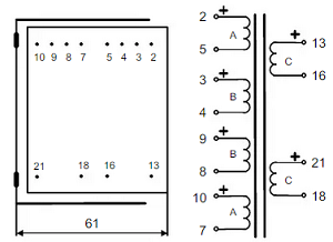
Simulating LUNDHAL frequency curves, using S-parametersFor this, we can not quickly explain here, how it's done in detail. But... it is not difficult to do, when you understand a little bit about software. If you only want to press buttons quickly, you will still see the example we give here, does the job for you indeed. When you like the results and want to do more with it, you need to work yourself through the basics of this. If doing so, and you get stuck, the schematic we give here for downloading, is always a good anchor, and you can try to modify it. That is easier as beginning from scratch. So what you need for this is, LTSPICE installed. This is freeware from Analog Devices company. Then, download the circuit example (link below here). For this, use the schematic we give you. You can only open it with LTSPICE. After opening, the program can edit the schematic, and it's even a good, free schematics drawing program. Logically the parts in the schematic have all values stored into them. So a coil has not only it's inductance stored, but also it's series resistance and parasitic capacitance, etc. (This was already done by me). Once a schematic is finished, and all components parts data is entered, LTSPICE can now run the schematic as an electrical simulation, and show the test results. That is why you see those two windows. At the analog devices website, there are some tutorials, etc, but this is a lot of work to read. First, to replicate the below picture quickly and live on your own PC, do the following: Do it exactly like this:
After some seconds, an (empty) curve chart window will appear. Now the fun begins. Move the cross hair precisely over the schematic, at any wire, node, or component. At some moments, the cross hair will change into a probe tip. If that happens, give a left mouse click, and a frequency chart will appear of that part you touched. Do this with the output of the circuit, and you see the chart as below here. When you click on the middle of a component, a current probe will appear. So you can measure the voltage and current wherever you like.
|
 I think it all started with the
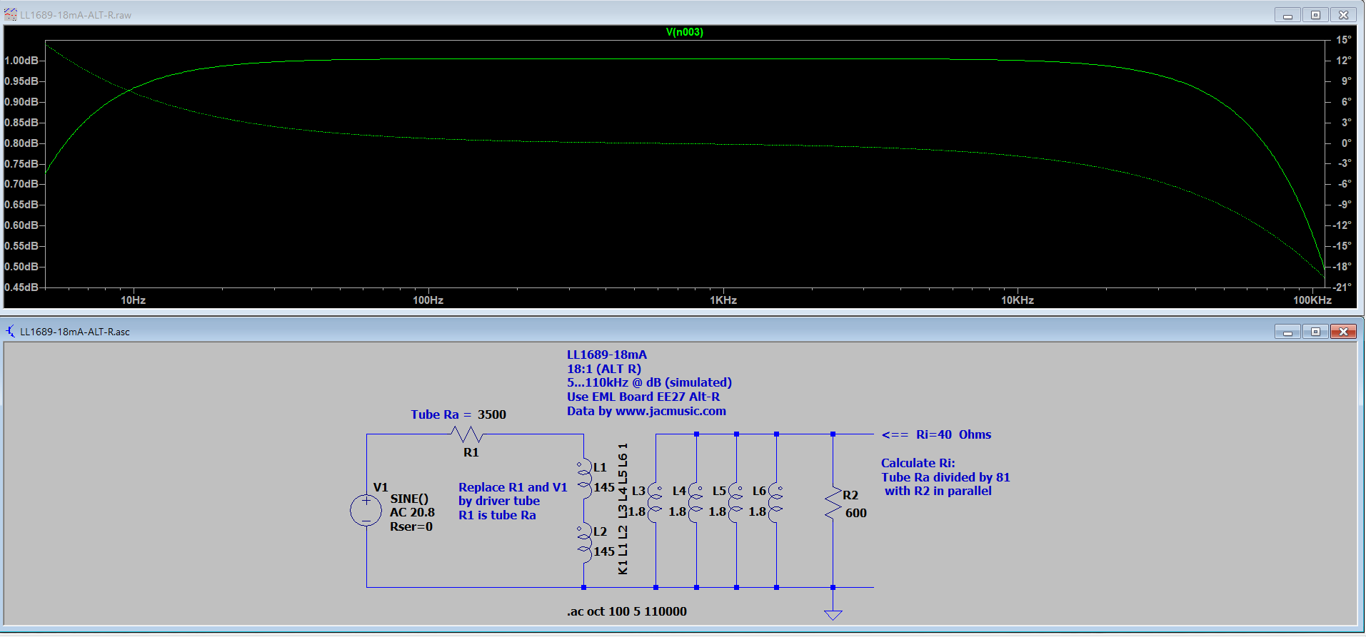
Notes:
- LL1660S vs. LL1660. The S (screened) Series transformers are internally wired differently. Though every 'ALT', of 'S' and 'none-S' can be converted to each other, you can not just take the connections of an 'S' und use it for 'none-S', or vice versa. Please ask if some nice configuration is missing, we can just add it on this page.
- ALT-J1, ALT-X1, etc. These are alternative connections, which are not in the data sheet.
- Use of LL1660 as anode choke. This works very nice. DC current and inductance need a little calculation, and the formula is given in the table. The intention is here, to use such a choke as anode choke, when you have it laying around anyway.
- Parafeed. The PPZ Series transformers are exclusively made for only this purpose. Parafeed requires an application note rather, and can not explained here quickly in detail. I believe Jack Elliano from Las Vegas was the first to use this elegant method. It uses two transformers, splitting the DC requirement and AC requirement, each into it's own transformer. The DC current of the SE tube is send into a choke, for which we have little requirements other than a low capacitance. Which means, it must still be an audio choke, but linearity is not important. The AC part is transferred by a transformer which is made for DC free operation. It has zero air gap, which is where the Z in the part number comes from. Such can be smaller, and have lower capacitance. Yet because of zero air gap, they have a very high inductance, even though they are small. So parafeed combines the best of two concepts. The drawback of having to use a coupling transformer is small, compared to overall much better transformer performance. AMORPHOUS core with Parafeed works excellent, because with amorphous we must always try to keep the DC load low, and with parafeed there is zero DC. Read more....
- Shielded (S) Version. These transformers have another pin lay out. It means in the data sheet they have their own "Alt" connection schemes. Though these schemes effectively do the same, they use another Index letter, to prevent mistakes.
- Grounded or none grounded RCA, vs. XLR output connector. As input solution, consider also the new Board EE24 for this. The best connectors are XLR. The most used connector is grounded RCA because this makes the electronics cost less. The price difference is not so much the connectors. This needs a balanced (symmetric) signal, which complicates the circuitry. However, a grounded RCA connector creates also an unwanted ground connection from the pre amplifier, to the power amplifier, and this is where trouble begins. This ground connection at the same time is also made via the mains cables, which is by law, and unavoidable. So the safety ground path, which always carries small (capacitive, or leakage) current, is in parallel with the outside shield of the RCA cable, which shield is also the signal return path. Needless to say, this may cause weird interaction, and when it does, it is hard to understand where the hum is coming from. Then, interrupting what we call the ground loop, is needed, and better create no ground loop in the first place. All tone transformers, offer this option! The best is using an XLR connector, because these work with a differential signal between XLR-2 and XLR-3, meaning it is not referred to ground any more, but one signal line is only referred to the other. At the transformer output, the lines for XLR-2 and XLR-3, are so to say floating. (It is nothing but a transformer output winding). Just in order to prevent some crazy high common mode signal, which can be 20...150Volts AC, the center of the winding is usually chassis grounded. With a grounded center, when the voltage of XLR-2 goes up vs ground, the voltage of XLR-3 goes down. (and vice versa). In other words, it becomes a true balanced output. The cable shield can still be grounded, and even when this re-introduces the ground loop, that doesn't matter any more, because the shield carries no audio signal. Only carries the small ground loop (hum) signal. Yet it's SHIELDING function is still existing. Regardless the better function, XLR is not very commonly used. In order to work balanced and be compatible with RCA equipment, an interesting option is to use isolated ground RCA connectors. This requires of course a "differential" drive signal, but a transformer output winding will provide that. So as the word says, with an isolated ground RCA connector, it's ground is not connected to the chassis, but has a separate solder lug. Like this, the ground loop is broken. In order to put signal on the cable still, we need a transformer winding. At the receiving end, the RCA connector may be grounded, or also isolated ground. In both cases, there is no electrical ground connection any more from the sender to the receiver, via the RCA connector. It is not as quite as elegant as XLR, but very close.
- FAKE XLR. This is not nice, but some "so called" Hi-fi companies fool you with that. The XLR Connectors are wired same as grounded RCA. Fake: Signal is on XLR2 only. XLR-3 is connected both to ground.
 Secret Schematics. This is really a RED FLAG. Do not a buy a tube amplifier with secret schematics. Not only is this illegal by the seller, it is also a problem in a repair case, when the seller is gone by the wind. (Google for: "Right to repair"). But seriously, do you really think a man with a solder iron can invent something new, all by himself, which is so great he must keep this a secret? Don't let them fool you with that. What is kept secret, is only what you needed to know, to judge the quality of his work before buying, to repair it afterwards. Ever since Julius Futterman, who patented the OTL circuit in the 1953, there was nothing very clever any more added to the world of tube schematics. Even the parafeed concept, now being rediscovered, was invented by Western Electric, almost 100 years ago now.
 - Microphonics is a difficult subject. These few lines here can not explain everything, but when this is new to you, try to do some of the calculations examples yourself. So what Signal (S) which goes into the tube stage? What is the Noise (N) added by the tube itself? What is the Signal to Noise Ratio (SNR) using a step down transformer, or not using it. These two numbers are what you need, and when you gave them in front of you and understand the calculations, it's the break though to understand this subject. The MOST important thing is, never spoil your signal to noise ratio, as this can not be reversed any more. You can reverse loss of low frequency for instance, but you can not reverse loss of signal to noise ratio. So if a tube appears microphonic, you can call it a bad tube, or a bad circuit design. This gets almost always confirmed, if one angry customer "can not use" a so called bad NOS tube, and sends it back. Then, the next owner may as well be totally happy with it, just because he has another, better amplifier. Most of the mistakes with microphonics are made with low level design of the amplifier, and really not with low tube quality. But we all know, in the end there is little other choice, as to do tube rolling, and it will help only a little bit. But what really helps very much, is not use a bad circuit design in the first place. In short, when there IS microphonics, you already HAVE a bad circuit design. With this I mean not how the amplifier looks from the outside, or what brand it is printed on it. Quality is something at the inside, not at the outside. It becomes visible only, when we look at the schematic. There is no other way to judge it.
ALWAYS, tube microphonics appear when you pass a signal level through a tube, which is capable of a lot more. For instance, it could do 200x more signal as in the circuit. So the same tube, now driving an attenuating Inter Stage or attenuating output transformer, will now be running at accordingly higher signal, in the same ratio as the transformer attenuation factor. That will reduce noise a lot! You will see the pieces fit together, when a typical pre-amp output transformer is LL1689, which has maximum 18x attenuation. 1/18 is 5.5%. Meaning only 5.5% of the original microphonics is left. So, tube microphonics may go from "smallest chassis noise audible" to "almost inaudible, even when you tap on the tube itself". The question remaining is not really where you get the extra signal from, to drive the transformer with 18x more signal as before. All tubes amplify anyway, and all pre-amps amplify much to much anyway. So even now, the volume control works as it should again. Which is maximum volume at maximum setting. Also the factor 18 reduces output impedance with a factor 18x18=324. So you get an incredible low output impedance of such a pre amp, which is so low, you can move the volume control from the input, to the output, where is belongs with a professional design. Driving a 600 Ohms wire wound pot meter with it. And no, wires of a wire wound potentiometer have no "sound". What does have a sound is a scratchy carbon pot meter at the input. Such a wire wound pot meter functions comparable to an auto transformer output. Via a few hundred wires, it switches the volume levels from one wire to the next. You will not "hear" these small steps, as you can with an auto transformer. These make often too large steps. Also, same as with an auto transformer, impedance and noise go down at lower volume, which is of course extremely beneficial, coming on top of the noise reduction we had already. Many times, after explaining this, people react fully confused, saying: Yes, but .... then I have a wire wound volume control at the output! Somehow they do not like those. Then if I ask, what advantage they expect from a carbon potmeter at the input, they do not know. Well, I also do not know. - Step down is useful when you have enough gain. This lowers output impedance, and any kind of tube noise, incl. microphonics. Read also notes about tube microphonics.
- Step up transformers are ideal when there is not enough overall gain. A driver tube for this, should be medium or low impedance. Or even more, for typical low gain, low impedance tubes, like 45, 2A3 or 300B, if used to drive a step up Inter Stage, this is a near perfect concept. A Step-Up Inter Stage lowers overall noise of the whole amplifier significantly, when this method leads to elimination of one tube stage. If just not enough gain this way, consider in addition to add a step up input transformer. Ideally programmable EE20 board, with LL1545 or LL1544, because it can select a whole range of gain. Like this, you can choose the input gain you need. By all means you will increase the overall noise of an amplifier with a step up input transformer. So not only use it when there is lack of gain, but also it will reduce overall noise.
- Overall Noise of the amplifier has always to do with not destroying the signal to noise ratio (SNR). This includes microphonics. Once SNR is destroyed, you can not recover it. This happens when passing a small signal through a noisy or microphonic tube. Pass a HIGH signal through the same a tube, and it will add only very little noise. So work always with higher signal. Of course, when this HIGHER signal has to come from an additional tube stage, you will not achieve a noise reduction, but increase overall noise of the whole amplifier. Consider for that reason always an input transformer if you can afford it. So you go into the amplifier, and create directly after the input, 2x or 4x Gain with a transformer. This gain you get free of noise, at the small cost of a transformer. Then, in some cases it can eliminate one tube stage (Take the most microphonic stage for that). Consider in addition a step-down Inter Stage, if the input transformer gives more overall gain as needed. That means ANOTHER noise reduction, and the situation improves another step. By doing these things right, an amplifier can be made which is dead-silent and has no microphonics. Whereas the same tubes, would give microphonics in an amplifier without the right circuit concept, and people blame it on the tubes.
- Desoldering the EE27 board. Lundahl transformers officially are not made for desoldering actions, so we can not say something else. Yet the EE27 board V3 and higher, has oval solder connections, which makes desoldering possible if you want to try it.
- Termination resistor, or Termination RC network. With all tone transformers, the high frequency range ends somewhere, outside the audible range. It ends with a normal roll off, when the transformer has a minimum load. Without load, the signal may swing up, before the roll off appears, this is called ringing or resonance. This is normal, and it is caused by the LC resonance of windings capacitance and windings inductance. It appears rather when the transformer is driven with a very low impedance, and when the signal is stepped up (more windings). If this appears so, either leave it as is, because this happens outside the audible range anyway, and likely no tone source will produce such frequency. This can be removed, if wanted, by adding a secondary load. The best place for such a load is at the transformer itself. For this purpose, the terminals Z1 and Z2 can be used to connect such a load. In some data sheets, a load value is recommended, either as Resistor, or as RC network. Before doing so, consider if it is necessary at all, by inspecting the signal with an oscilloscope, and drive the transformer with a 5kHz square wave. If there is no ringing (very short resonance) at the edges, nothing needs to be done. Alternatively, increase the oscillator frequency, as the transformer will handle it, and it can be seen if the signal swings up at a specific (resonance) frequency, before roll off begins. If it does swing up, this can be damped by a load. If it does not swing up more than 30%, nothing needs to be done.
- Board Positioning. The boards can not be soldered wrong on the transformers, apart with the Anode Chokes LL1667, LL1668. The orientation is always with the text "(C) Emissionlabs" to the top, so where the type number label is on the transformer.
- Fault Finding with the EE27 Board. Almost every case of a suspected "shorted transformer", in the end always turned out to be a wiring error, or a concept mistake. Here, the EE27 board is very beneficial, because we can quickly verify if the transformer is ok. For this, always make a "before" and "after" picture, so in case the problem suddenly is gone afterwards, you can see then, what is the difference between those pictures. So provided, pictures were made, the procedure is like this: Take off the connection wires, and open all bridges. However, the inductance of the coils can damage the multimeter. To prevent this, we short one winding, it doesn't matter which one we take for this. We use the solder bridges for this. Close bridge 55 and 56. For an "S" type transformer and normal transformer, test points are different. For unshielded (none-S) Type, test resistance between: B-D, A-E, F-H, K-Q, C-P, C-Q, D-P, D-Q, E-P, E-Q, F-P, F-Q. For S-Type: B-D, A-E, F-H, P-Q, K-M, Q-S, C-K, C-M, D-K, D-M, E-K, E-M, F-K, F-M, C-Q, C-S, D-Q, D-S, E-Q. Each test must give "open connection" and then the transformer has no shorts. Finally, remember to open bridge 55 and 56 again. If the problem remains, it is not caused by the transformer itself.
- About PARAFEED. About the Western Electric 92A, a remarkable parafeed amplifier.
 Wow! You made it until here :)
This is about the Western Electric 92A from 1935, driving a pair of 300A with a PARAFEED to Push-Pull transformer.
Search the table above here for "parafeed". There are only some parafeed to output configurations added by me, but when you are interested in a parafeed to PP, let me know, sure the EE27 board can do it.
300A was in production only very short, and replaced by 300B, which is essentially the same tube, but 300B has not this bajonett side pin on the UX4 socket like 300A has.
Note, the transformer schematic suggests a double windings package, same as Lundahl is doing, but I only expect this. Perhaps somebody has both primary windings in series. This reduces capacitance. Here is the full schematic. WE92A has one of the nicest schematics ever made. It has very intelligent schematics, such as C9 and C10 at the 300A, which I think are to increase the bandwidth of the output transformer. Make also good note of the PARAFEED schematic of the 202A tube. Parafeed is normally done with a choke and a zero-DC current output transformer. Now here at WE they did something interesting, they use a very high anode resistor R10, to feed this little 262A tube, from a VERY high voltage. This effectively turns R10 into a current source. Not an ideal one, but still a very good one. Almost like a choke, but not with the problems chokes had in 1935. The return path of the AC signal is not to ground, but look what they are doing: To the cathode of the 202A. Some like to call this "Ultra Path" today. But it is like I always say, there were no more new tube circuits invented ever since Julius Futterman invented the OTL. Some advantage I see here, the power supply hum gets cancelled out with the right balance of C1 and C2. Any power supply hum which finds it's way via R10, into the parafeed transformer, would flow via C1, and generate a signal across the 262 tube's cathode resistor. To make this work, C2 must be in a certain ratio to C1, which is as we can see here: 16x. This is a truly remarkable schematic, almost 100 years old. Here is a full copy.