Since 1993 Copyright Notice
Electron Engine ™
Printed Circuit Boards by Emissionlabs
EE27 Version V3.0 Matrix connection board for:
LL1660, LL1660S, LL1667, LL1668, LL1671, LL1677, LL1692A, LL1689, LL2731, LL2745, LL2754, LL2763, LL2766
Unintended, this became a small application note for this transformer family as well :)
How to choose the transformer.
These are all wound like 1+1+1+1 : n+n. (n=Ratio). To get a first idea for a choice, do not compare everything with each other. Better is, to make those following steps, and you soon find the right transformer.
- Do you need a transformer, with a SMALL step ratio? (For inter stage mainly). It is found in TABLE A. (just below here)
- Or, Do you need a transformer, with a LARGE step ratio? (To achieve low output impedance). This is found in Table B
- A special one is the 300B / 2A3 interstage. So a 300B or 2A3, driving an interstage transformer, in Table C
Once you have found the transformer type, from tables A, B, C, you can select the step ratio, and all other things from TABLE D
Example: Suppose you need SE to SE, 1:1. This is a low ratio. Look in TABLE A. You can see there L1671, ALT-S. Still, when you have it at the bench, you could also try 1:2 (Alt.T). That is just a matter of changing a few solder jumpers.
About the EE27 matrix board.
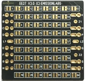 The Lundahl data sheets are based on hand wiring the transformers, but these have relatively small pins, and the result often looks not very nice. Moreover, with so many pins, if a wiring error is made, the transformer may have bad sound, or not work at all. In case of bad sound, it is not obvious to find the error, or realize at all you have an error. Also, re wiring, just to try another configuration, users normally avoid it. This is a pity, missing such a nice advantage of this transformer family.
With the EE27 board, wiring mistakes are history, and trying out another configuration is done quickly, and also interesting and fun to do. We have all known Lundahl configurations in the data table below here. Also there is clear data for how to wire those for RCA or XLR, if that applies. The EE27 boards can do all data sheet configurations, but also practically any new configuration as well. Since it is a matrix, virtually any configuration is possible, also new ones, not in the data sheet. Besides, in case you need application help, we can much easier understand each other. Normally we need only a picture of the mounted board.
TABLE A: Small gain. Or small step down, by reversing the transformer. For inter stage or line out. Use with low gain tubes. Examples of some possibilities. |
||||||||||
Line |
Show configs |
PP to PP-Inter Stage |
SE to Output |
SE to SE-Inter Stage |
PP to Output |
SE to SE-InterStage |
SE to PP-Inter stage |
|||
01 |
Alt.M'' (2.25+2.25 :2+2)
|
Alt.Q (4.5 :1)
|
Alt.T (2: 4.5)
|
Alt.N (2.25+2.25 :1)
|
Alt.S (4 : 4.5)
|
Alt.V 2.25 : 2+2)
|
||||
02 |
Alt.M (2+2 : 2+2)
|
Alt.Q (4 : 1)
|
Alt.T (1 : 2)
|
Alt.N (2 +2 : 1 )
|
Alt.S (1 : 1)
|
Alt.V (1 : 1+1)
|
||||
03 |
Alt.M (1.75 + 1.75 : 2+2)
|
Alt.Q (3.5 : 1)
|
Alt.T (2 : 3.5)
|
Alt.N (1.75 + 1.75 : 1 )
|
Alt.S (4 : 3.5)
|
Alt.V (1.75 : 2 + 2 )
|
||||
| TABLE B: High step down ratio. This gives low output impedance. Use with high gain tubes. Examples of some possibilities. |
||||||||||
| Line | Show configs |
PP to Output |
PP to Output |
PP to Output |
PP to Output |
SE to Output |
SE to Output |
SE to Output |
SE to Output |
|
01 |
Alt.M (9+9 :4)
|
Alt.N (9+9 :2)
|
Alt.O (9+9 :1)
|
Alt.P (18:4)
|
Alt.Q (18:2)
|
Alt.R (18:1)
|
||||
02 |
Alt.M (8+8 :8)
|
Alt.N (8+8 :4)
|
Alt.O (8+8 :2)
|
Alt.P (8:4)
|
Alt.Q (8:2)
|
Alt.R (8:1)
|
||||
03 |
Alt.M (2.8+2.8 :4)
|
Alt.N (2.8+2.8 :2)
|
Alt.O (2.8+2.8 :1)
|
Alt.P (5.6:4)
|
Alt.Q (5.6:2)
|
Alt.R (5.6:1)
|
||||
04 |
LL2766 | ALT.A (79:2) | ALT.B (79:3) | ALT.C (79:4) | ALT.D (79:6) | ALT.A (79:2) | ALT.B (79:3) | ALT.C (79:4) | ALT.D (79:6) | |
| TABLE C 300B-2A3 inter stage. Specially made to drive it with 300B or 2A3. Can also run with other tubes (read below). | ||||||||||
Alt. A
|
Dedicated to be used as an inter stage, using 300B, 2A3 or 45, AD1, PX4, PX25, etc as a driver, by the SAKUMA principle. This elegant way to reduce distortion, uses no feedback. Published by Ratheiser in 1950, refined by Mr. Sakuma from Japan, who devoted half of his life to this. (More about it here) | |||||||||
TABLE D. All known configurations of EE27 Version V3.
Line |
P/N |
Use |
Config |
ALT |
Max. V-Out (RMS) |
Max DC current |
Links |
Attach |
Notes |
|---|---|---|---|---|---|---|---|---|---|
001 |
LL1660-PP-S
(ONLY: Shielded S-TYPE!) |
PP to Interstage-PP |
2.25 + 2.25 : 2+2 |
A |
2x 114V |
15% of rated |
1, 2, 8, 13, 17, 25, 26, 30, 36, 40, 45, 50, 63, 64. | V+=M, In+=T, In-=P, Out+=C, Out-=G, Gnd=L1+L2 | Shielded (S) version has different pin connections. |
002 |
LL1660-PP-S
(ONLY: Shielded S-TYPE!) |
PP to XLR Output |
2.25 + 2.25 : 2+2 |
A |
2x 114V |
15% of rated |
1, 2, 8, 13, 17, 25, 26, 30, 36, 40, 45, 50, 63, 64. | V+=M, In+=S, Gnd-In=L2, XLR1+=C, XLR2=G, XLR3=L1 | Shielded (S) version has different pin connections. See: 'Shielded Type' Note. Also see Reversed Appication. |
003 |
LL1660-xxmA-S
(ONLY: Shielded S-TYPE!) |
SE to Interstage-PP |
2.25 : 2+2 |
B |
2x 114V |
1.8x rated |
1, 2, 8, 13, 17, 25, 26, 30, 36, 40, 46, 50, 55, 61, 63, 64. | V+=M, In+=S, Out+=C, Out-=G, Gnd=D+Q+L1+L2 | Shielded (S) version has different pin connections. See: 'Shielded Type' Note. Also see Reversed Appication. |
004 |
LL1660-xxmA-S
(ONLY: Shielded S-TYPE!) |
SE to XLR Output |
2.25 : 2+2 |
B |
2x 114V |
1.8x rated |
1, 2, 8, 13, 17, 25, 26, 30, 36, 40, 46, 50, 55, 61, 63, 64. | V+=M, In+=S, Gnd-In=L2, XLR1+=C, XLR2=G, XLR3=L1 | Shielded (S) version has different pin connections. See: 'Shielded Type' Note. Also see Reversed Appication. |
005 |
LL1660-xxmA-S
(ONLY: Shielded S-TYPE!) |
SE to Interstage-SE |
4 : 4.5 |
S |
250V |
Same as rated |
3, 5, 12, 17, 28, 30, 43, 46, 48, 55, 60 | V+=C, In+=G, Out+=T, Gnd=P | Shielded (S) version has different pin connections. See: 'Shielded Type' Note |
006 |
LL1660-xxmA-S
(ONLY: Shielded S-TYPE!) |
SE to Interstage-SE |
2 : 4.5 |
T |
250V |
2x rated |
2, 9, 13, 15, 24, 27, 38, 40, 43, 46, 47, 55, 60 | V+=C, In+=G, Out+=T, Gnd=P | Shielded (S) version has different pin connections. See: 'Shielded Type' Note This needs low Rp driver tube |
007 |
LL1660-xxmA-S
(ONLY: Shielded S-TYPE!) |
SE to Interstage-PP |
2.25 : 2+2 |
V |
Use LL1660-xxmA-S, ALT-B to get this scheme. |
||||
008 |
LL1660-PP-Z(Parafeed transformer) |
Parafeed to SE or RCA Output |
4.5 : 1 |
Q |
57V |
none |
R-RCA: 2, 3, 9, 10, 14, 15, 17, 18, 56, 61 | V+=Q, Cap+=K, Out+=G, Out-=C |
Reduces noise by factor 4.5, and reduces Rp by factor 20 See: Parafeed Connection Note - See: RCA Connection Note |
009 |
LL1660-PP |
PP to Interstage-PP |
2.25+2.25 : 2+2 |
M'' |
2x 125V |
13% of rated |
1, 2, 8, 13, 17, 25, 26, 30, 53, 58 | V+=Q, In+=T, In-=P, Out+=G, Out-=C | See Reversed Appication. |
010 |
LL1660-PP |
PP to XLR Output |
2.25+2.25 : 1 |
N |
57V |
13% of rated |
1, 2, 3, 9, 14, 15, 17, 18, 45, 47, 53, 58 | V+=Q, In+=T, In-=P, XLR1=L1, XLR2=G, XLR3=C | Reduces noise by factor 2.3, and reduces Rp by factor 5.1. See: XLR Connection Note1 - See Reversed Appication. |
011 |
LL1660-PP |
PP to grounded RCA Output |
2.25+2.25 : 1 |
N |
57V |
13% of rated |
2, 3, 9, 10, 14, 15, 17, 18, 53, 58. | V+=Q, In+=T, In-=P, Out+=G, Gnd=C | Reduces noise by factor 2.3, and reduces Rp by factor 5.1. See: RCA Connection Note1 - See Reversed Appication. |
012 |
LL1660-xxmA |
SE to SE or RCA Output |
4.5 : 4 |
P |
228V |
88% of rated |
2, 8, 13, 17, 25, 30, 56, 61 | V+=Q, In+=K, Out+=G, Out-=C | Alt P, same as LL1689 data sheet. See: RCA Connection Note |
013 |
LL1660-xxmA |
SE to XLR Output |
4.5 : 4 |
P |
228V |
88% of rated |
2, 8, 13, 17, 25, 26, 30, 56, 61 | V+=Q, In+=K, XLR1=L1, XLR2=G, XLR3=C | Alt P, same as LL1689 data sheet. |
014 |
LL1660-xxmA |
SE to SE or RCA Output |
4.5 : 2 |
X4 |
114V |
88% of rated |
4, 7, 13 ,20, 25, 28, 30, 32, 39, 56, 61 | V+=Q, In+=K, Out+=G, Out-=C | Reduces noise by factor 2.2 and reduces Rp by factor 5 |
015 |
LL1660-xxmA |
SE to XLR Output |
4.5 : 2 |
X4 |
114V |
88% of rated |
4, 7, 13 ,16, 20, 25, 28, 30, 32, 39, 56, 61 | V+=Q, In+=K, XLR2=G, XLR3=C | Reduces noise by factor 2.2 and reduces Rp by factor 5 |
016 |
LL1660-xxmA |
SE to SE or RCA Output |
4.5 : 1 |
Q |
57V |
88% of rated |
2, 3, 9, 10, 14, 15, 17, 18, 56, 61 | V+=Q, In+=K, Out+=G, Out-=C | Reduces noise by factor 4.5, and reduces Rp by factor 20 |
017 |
LL1660-xxmA |
SE to XLR Output |
4.5 : 1 |
Q |
57V |
88% of rated |
1, 2, 3, 9, 10, 14, 15, 17, 18, 56, 61 | V+=Q, In+=K, XLR2=G, XLR3=C | Reduces noise by factor 4.5, and reduces Rp by factor 20 |
018 |
LL1660-PP-Z-S
|
Parafeed to SE or RCA Output |
4.5 : 1 |
X2 |
57V |
none |
Shielded (S) version has different pin connections. See: 'Shielded' Note - See: RCA Connection Note - See: Parafeed Connection Note - | ||
019 |
LL1660-xxmA |
SE to Interstage-SE |
4 : 4.5 |
S |
250V |
Same as rated |
1, 3, 5, 12, 17, 28, 30, 53, 58 | V+=C, In+=G, Out+=T, Gnd=P | No Gain |
020 |
LL1660-xxmA |
SE to Interstage-PP |
2.25 : 2+2 |
V |
2x 114V |
1.8x rated |
2, 8, 13, 17, 25, 26, 30, 43, 51, 56, 58 | V+=K, In+=Q, Out+=C, Out-=G, Gnd=D | Low impedance output, but requires also a low impedance driver tube. |
021 |
LL1660-xxmA |
SE to Interstage-SE |
2.25 : 2 |
X6 |
114V |
1.8x rated |
2, 9, 13, 15, 24, 27, 38, 40, 46, 48, 53, 61, | V+=K, In+=Q Out+=G, Gnd=C |
See: New configurations - See Reversed Appication. |
022 |
LL1660-xxmA |
SE to Interstage-PP |
2.25 : 1+1 |
X1 |
2x57V |
1.8x rated |
2, 8, 13, 17, 25, 26, 30, 56, 61 | V+=K, In+=Q Out+=C, Out-=G, Gnd=D | Low impedance output, but can work with medium to high impedance driver tube. - See Reversed Appication. |
023 |
LL1660-xxmA |
SE to SE or RCA Output |
2.25 : 1 |
X5 |
57V |
1.8x rated |
4, 5, 7, 8, 12, 13, 19, 20, 43, 51, 56, 58. | V+=Q, In+=K, Out+=G, Out-=C | Reduces noise by factor 2.2 and reduces Rp by factor 5. For lower impedance driver tubes. See: RCA Connection Note - See Reversed Appication. |
024 |
LL1660-xxmA |
SE to Interstage-SE |
2 : 4.5 |
T |
250V |
2x rated |
2, 9, 13, 15, 24, 27, 38, 40, 53, 58 | V+=C, In+=G, Out+=T, Gnd=P | Step up. Needs low Rp driver tube |
025 |
LL1660-xxmA |
SE to Interstage-SE |
2 : 2.25 |
X7 |
125 |
2x rated
|
2, 9, 13, 15, 24, 27, 38, 40, 46, 48, 53, 61 | Out+=T, Gnd=P | See: New configurations |
026 |
LL1660-xxmA |
SE to Interstage-SE |
1 : 1.5 |
X3 |
3, 5, 7, 12, 18, 29, 53, 58 | V+=C, In+=G, Out+=T, Gnd=P | Small step up factor. Can work with Medium Rp driver tube. Untested, but should work good. See: New configurations |
||
027 |
LL1667 |
Anode Choke |
Coils in Parallel |
PAR |
2, 10, 15, 17 | V+= A, Anode=E.
Choke from A to E |
|
||
028 |
LL1667 |
Anode Choke |
Coils in Series |
SER |
5, 10 | V+= A, Anode=E. Or, Choke from A to E |
Rated data. | ||
029 |
LL1667 |
Anode Choke |
Push Pull |
PP |
2, 7 | V+= A, Anode= D, H | Rated data. | ||
030 |
LL1668 |
Anode Choke |
Coils in Parallel |
PAR |
2, 10, 15, 17 | V+= A, Anode=E. Or, Choke from A to E |
|
||
031 |
LL1668 |
Anode Choke |
Coils in Series |
SER |
5, 10 | V+= A, Anode=E. Choke from A to E | Rated data. | ||
032 |
LL1668 |
Anode Choke |
Push Pull |
PP |
2, 7 | V+= A, Anode= D, H | Rated data. | ||
033 |
LL1677-xxmA |
SE to Interstage-SE |
1 : 2 |
A |
same as rated |
3, 5, 12, 17, 28, 30, 47, 51, 53, 58 | V+=C, In+=G, Grid=P, Gnd=L2 | Step up. Needs low Rp driver tube | |
034 |
LL1671-PP |
PP to Interstage-PP |
2+2 : 2 |
M'' |
1, 2, 8, 13, 17, 25, 26, 30, 53, 58 | V+=Q, In+=T, In-=P, Out+=G, Out-=C | - | ||
035 |
LL1671-PP |
PP to XLR Output |
2+2 : 1 |
N |
1, 2, 3, 9, 14, 15, 17, 18, 45, 47, 53, 58 | V+=Q, In+=T, In-=P, XLR1=L1, XLR2=G, XLR3=C | See: XLR Connection Note | ||
036 |
LL1671-xxmA |
PP to grounded RCA Output |
2+2 : 1 |
N |
2, 3, 9, 10, 14, 15, 17, 18, 53, 58. | V+=Q, In+=T, In-=P, Out+=G, Gnd=C | Reduces noise by factor 2, and reduces Rp by factor 4. See: RCA Connection Note |
||
037 |
LL1671-xxmA |
SE to Interstage-PP |
1 : 1+1 |
V |
2, 8, 13, 17, 25, 26, 30, 43, 51, 56, 58 | V+=K, In+=P, Out+=C, Out-=G, Gnd=D | - | ||
038 |
LL1671-xxmA |
SE to SE or RCA Output |
4 : 1 |
Q |
2, 3, 9, 10, 14, 15, 17, 18, 56, 61 | V+=Q, In+=K, Out+=G, Out-=C | Reduces noise by factor 4, and reduces Rp by factor 16. |
||
039 |
LL1671-xxmA |
SE to XLR Output |
4 : 1 |
Q |
1, 2, 3, 9, 10, 14, 15, 17, 18, 56, 61 | V+=Q, In+=K, XLR2=G, XLR3=C | Reduces noise by factor 4, and reduces Rp by factor 16. | ||
040 |
LL1671-PP-Z(Parafeed transformer) |
Parafeed to SE or RCA Output |
1 : 1 |
S |
none |
1, 3, 5, 12, 17, 28, 30, 53, 58 |
In+=G, Gnd=L1+L2, Out+=21 | See: Parafeed Connection Note | |
041 |
LL1671-xxmA |
SE to Interstage-SE |
1 : 1 |
S |
Same as rated |
1, 3, 5, 12, 17, 28, 30, 53, 58 |
V+=C, In+=G, Out+=T, Gnd=P | - | |
042 |
LL1671-xxmA |
SE to Interstage-SE |
1 : 2 |
T |
2, 9, 13, 15, 24, 27, 38, 40, 53, 58 | V+=C, In+=T, In+=G, Out+=T, Gnd=P | 2x Step up. Needs low Rp driver tube. | ||
043 |
LL1671-xxmA |
SE to Interstage-PP |
1 : 1+1 |
V |
2, 8, 13, 17, 25, 26, 30, 43, 51, 56, 58 | V+=K, In+=P, Out+=C, Out-=G, Gnd=D | - | ||
044 |
LL1671-xxmA |
SE to Interstage-SE |
1 : 1.3 |
X3 |
3, 5, 7, 12, 18, 29, 53, 58 | V+=C, In+=G, Out+=T, Gnd=P | Small step up factor. Can work with Medium Rp driver tube. Untested, but should work good. See: New configurations |
||
045 |
LL1689-PP |
PP to SE or RCA Output |
2.25 +2.25 : 1 |
M |
2, 8, 13, 17, 25, 30, 53, 58 | V+=Q, In+=T,In=P, Out+=G, Out-=C | Reduces noise by factor 2.3, and reduces Rp by factor 5.3 See: RCA Connection Note - See Reversed Appication. |
||
046 |
LL1689-PP |
PP to XLR Output |
2.25 +2.25 : 1
|
M |
2, 8, 13, 17, 25, 26, 30, 53, 58 | V+=Q, In+=T,In=P, XLR1=L1, XLR2=G; XLR3=C | Reduces noise by factor 2.3, and reduces Rp by factor 5.3 - See Reversed Appication. | ||
047 |
LL1689-PP |
PP to SE or RCA Output |
4.5+4.5 : 1 |
N |
2, 4, 6, 7, 9, 13, 20, 25, 28, 53, 58. | V+=Q, In+=T, In=P, Out+=H, Out-=D | Reduces noise by factor 4.5, and reduces Rp by factor 20 See: RCA Connection Note |
||
048 |
LL1689-PP |
PP to XLR Output |
4.5+4.5 : 1 |
N |
2, 4, 6, 7, 9, 13, 20, 25, 28, 53, 58. |
V+=Q, In+=T, In=P, XLR1=L1, XLR2=H; XLR3=D | Reduces noise by factor 4.5, and reduces Rp by factor 20 | ||
049 |
LL1689-PP-Z(Parafeed transformer) |
Parafeed to Headphone or RCA Output |
4.5 : 1 |
P |
none |
2, 8, 13, 17, 25, 26, 30, 56, 61 |
V+=Q, Capacitor=K, Out+=to Headphone or RCA, Out-=Ground | Reduces noise by factor 4.5, and reduces Rp by factor 20 |
|
050 |
LL1689-PP-Z(Parafeed transformer |
Parafeed to Headphone or RCA Output |
9 : 1 |
Q |
none |
2, 4, 6, 7, 9, 13, 20, 25, 28, 56, 61. | V+=Q, Capacitor=K, Out+=to Headphone or RCA, Out-=Ground | Reduces noise by factor 9, and reduces Rp by factor 81 |
|
051 |
LL1689-PP-Z(Parafeed transformer |
Parafeed to Headphone or RCA Output |
18 : 1 |
R |
none |
2, 3, 9, 10, 14, 15, 17, 18, 56, 61 | V+=Q, Capacitor=K, Out+=to Headphone or RCA, Out-=Ground | Reduces noise by factor 18, and reduces Rp by factor 324 |
|
052 |
LL1689-xxmA |
PP to SE or RCA Output |
9+9 : 1 |
O |
15% of rated |
2, 3, 9, 10, 14, 15, 17, 18, 53, 58 | V+=Q, In+=K, In-=T, Out+=G, Out-=C | Reduces noise by factor 9, and reduces Rp by factor 81 See: RCA Connection Note |
|
053 |
LL1689-xxmA |
SE to RCA Output |
18 : 4 |
P |
Same as rated |
2, 8, 13, 17, 25, 26, 30, 56, 61 |
V+=Q, In+=K, Out+=G, Out-=C | Reduces noise by factor 4.5, and reduces Rp by factor 20 See: RCA Connection Note |
|
054 |
LL1689-xxmA |
SE to XLR Output |
18 : 4 |
P |
Same as rated |
2, 8, 13, 17, 25, 26, 30, 56, 61 | V+=Q, In+=K, XLR1=L1, XLR2=G, XLR3=C | Reduces noise by factor 4.5, and reduces Rp by factor 20 | |
055 |
LL1689-xxmA |
SE to RCA Output |
18 : 2 |
Q |
Same as rated |
2, 4, 6, 7, 9, 13, 20, 25, 28, 56, 61. | V+=Q, In+=K, Out+=G, Out-=C | Reduces noise by factor 9, and reduces Rp by factor 81 See: RCA Connection Note |
|
056 |
LL1689-xxmA |
SE to XLR Output |
18 : 2 |
Q |
Same as rated |
2, 4, 6, 7, 9, 13, 20, 25, 28, 56, 61 | V+=Q, In+=K, XLR1=L1, XLR2=G, XLR3=C | Reduces noise by factor 9, and reduces Rp by factor 81 | |
057 |
LL1689-xxmA |
SE to RCA Output |
18 : 1 |
R |
Same as rated |
2, 3, 9, 10, 14, 15, 17, 18, 56, 61 | V+=Q, In+=K, Out+=G, Out-=C | Reduces noise by factor 18, and reduces Rp by factor 324 See: RCA Connection Note |
|
058 |
LL1692A-PP |
PP to Interstage-PP |
1.75+1.75 : 2+2 |
M |
2x 240V |
2, 8, 13, 17, 25, 26, 30, 53, 58 |
V+=Q, In+=T, In-=P, Out+=G, Out-=C, GND=L1 | ||
059 |
LL1692A-PP |
PP to XLR |
1.75+1.75 : 2+2 |
M'' |
2x 240V |
1, 2, 3, 9, 14, 15, 17, 18, 45, 47, 53, 58 | V+=Q, In+=T, In-=P, XLR1=L1, XLR2=G, XLR3=C | This is based on LL1671 Data sheet | |
060 |
LL1692A-PP |
PP to SE or RCA Output |
1.75+1.75 : 1 |
N |
120V |
2, 3, 9, 10, 14, 15, 17, 18, 56, 61 | V+=Q, In+=T, In-=P, Out+=G, Gnd=C | Reduces noise by factor 1.8, and reduces Rp by factor 3.1 See: RCA Connection Note |
|
061 |
LL1692A-PP |
PP to XLR Output |
1.75+1.75 : 1 |
N |
120V |
1, 2, 3, 9, 14, 15, 17, 18, 45, 47, 53, 58. | V+=Q, In+=T, In-=P, XLR1=L1, XLR2=G, XLR3=C | Reduces noise by factor 1.8, and reduces Rp by factor 3.1 See: XLR Connection Note |
|
062 |
LL1692A-xxmA |
SE to RCA Output |
3.5 : 1 |
Q |
50V |
1.16x rated |
2, 3, 9, 10, 14, 15, 17, 18, 56, 61 | V+=Q, In+=K, Out+=H, Out-=F | Reduces noise by factor 3.5, and reduces Rp by factor 12 See: RCA Connection Note |
063 |
LL1692A-xxmA |
SE to XLR Output |
3.5 : 1 |
Q |
50V |
1.16x rated |
2, 3, 9, 10, 14, 15, 17, 18, 56, 61 | V+=Q, In+=K, Gnd=L2, XLR1=L1, XLR2=H, XLR3=F | Reduces noise by factor 3.5, and reduces Rp by factor 12 |
066 |
LL1692A-PP-Z(Parafeed transformer) |
Parafeed to SE or RCA Output |
4 : 3.5 |
S |
none |
1, 3, 5, 12, 17, 28, 30, 53, 58 |
In+=G, Gnd=L1+L2, Out+=21 | Reduces noise by factor 1.1, and reduces Rp by factor 1.3 See: Parafeed Connection Note See: RCA Connection Note |
|
064 |
LL1692A-xxmA |
SE to Interstage-SE |
4 : 3.5 |
S |
Same as rated |
1, 3, 5, 12, 17, 28, 30, 53, 58 | V+=C, In+=G, Out+=T, Gnd=P | Reduces noise by factor 1.1, and reduces Rp by factor 1.3 | |
065 |
LL1692A-xxmA |
SE to Interstage-SE |
2 : 3.5 |
T |
2, 7, 13, 14, 28, 20, 46, 47, 53, 58 | V+=C, In+=G, Out+=T, Gnd=L2 | - | ||
067 |
LL1692A-xxmA |
SE to Interstage-PP |
1.75 : 2+2 |
V |
2, 8, 13, 17, 25, 26, 30, 56, 58 | V+=K, In+=P, Gnd=L1, Grid1=G, Grid2=C | - | ||
068 |
LL2745-PP |
PP to SE or RCA Output |
1.4+1.4 : 2 |
M |
2, 8, 13, 17, 25, 26, 30, 53, 58 | V+=Q, In+=T, In-=P, Out+G, Out-=C | See: RCA Connection Note | ||
069 |
LL2745-PP |
PP to SE or RCA Output |
1.4+1.4 : 1 |
N |
5, 8, 13, 20, 22, 24, 26, 27, 29, 53, 58 | V+=Q, In+=T, In-=P, Out+=H, Out-=F | Reduces noise by factor 1.4, and reduces Rp by factor 2 See: RCA Connection Note |
||
070 |
LL2745-PP |
PP to SE or RCA Output |
2.8+2.8 : 1 |
O |
2, 3, 9, 10, 14, 15, 17, 18, 53, 58 | V+=Q, In+=T, In-=P, Out+=H, Out-=F | Reduces noise by factor 2.8, and reduces Rp by factor 7.8 See: RCA Connection Note |
||
071 |
LL2745-PP |
PP to XLR Output |
1.4+1.4 : 2 |
M |
2, 8, 13, 17, 25, 26, 30, 53, 58 | V+=Q, In+=T, In-=P, XLR1=L1, XLR2=G, XLR3=C | - | ||
072 |
LL2745-PP |
PP to XLR Output |
1.4+1.4 : 1 |
N |
5, 8, 13, 20, 22, 24, 26, 27, 29, 53, 58 | V+=Q, In+=T, In-=P, XLR1=L1, XLR2=H, XLR3=F | Reduces noise by factor 1.4, and reduces Rp by factor 2 | ||
073 |
LL2745-PP-Z(Parafeed transformer) |
Parafeed to RCA |
5.6 : 1 |
R |
2, 3, 9, 10, 14, 15, 17, 18, 56, 61 | CAP-In=Q, V+=K, Out+=H, Out-=F | Reduces noise by factor 5.6, and reduces Rp by factor 31 See: Parafeed Connection Note - See: RCA Connection Note |
||
074 |
LL2745-xxmA |
SE to RCA Output |
1.4 : 1 |
P |
2, 8, 13, 17, 25, 26, 30, 56, 61 | V+=Q, In+=K, Out+=G, Out-=C | Reduces noise by factor 1.4, and reduces Rp by factor 2. See: RCA Connection Note |
||
075 |
LL2745-xxmA |
SE to RCA Output |
2.8 : 1 |
Q |
2, 4, 7, 9, 13, 20, 25, 28, 56, 61 | V+=Q, In+=K, Out+=G, Out-=C | Reduces noise by factor 2.8, and reduces Rp by factor 7.8. See: RCA Connection Note |
||
076 |
LL2745-xxmA |
SE to RCA Output |
5.6 : 1 |
R |
2, 3, 9, 10, 14, 15, 17, 18, 56, 61 | V+=Q, In+=K, Out+=G, Out-=C | Reduces noise by factor 5.6, and reduces Rp by factor 31. See: RCA Connection Note |
||
077 |
LL2745-xxmA |
SE to SE Interstage |
1.4 : 1 |
P |
2, 8, 13, 17, 25, 26, 30, 56, 61 | V+=Q, In+=K, Out+=G, Gnd=C | Reduces noise by factor 1.4, and reduces Rp by factor 2 | ||
078 |
LL2745-xxmA |
SE to SE Interstage |
2.8 : 1 |
Q |
2, 4, 7, 9, 13, 20, 25, 28, 56, 61 | V+=Q, In+=K, Out+=G, Gnd=C | Reduces noise by factor 2.8, and reduces Rp by factor 7.8 | ||
079 |
LL2745-xxmA |
SE to SE Interstage |
5.6 : 1 |
R |
2, 3, 9, 10, 14, 15, 17, 18, 56, 61 | V+=Q, In+=K, Out+=G, Gnd=C | Reduces noise by factor 5.6, and reduces Rp by factor 31 | ||
080 |
LL2745-xxmA |
SE to XLR Output |
1.4 : 1 |
P |
2, 8, 13, 17, 25, 26, 30, 56, 61 | V+=Q, In+=K, XLR1=L1, XLR2=G, XLR3=C | Reduces noise by factor 1.4, and reduces Rp by factor 2 | ||
081 |
LL2745-xxmA |
SE to XLR Output |
2.8 : 1 |
Q |
2, 4, 6, 7, 9, 13, 20, 25, 28, 56, 61 | V+=Q, In+=K, XLR1=L, XLR2=H, XLR3=F | Reduces noise by factor 2.8, and reduces Rp by factor 7.8 | ||
082 |
LL2745-xxmA |
SE to XLR Output |
5.6 : 1 |
R |
2, 3, 9, 10, 14, 15, 17, 18, 56, 61 | V+=Q, In+=K, XLR2=G, XLR3=C | Reduces noise by factor 5.6, and reduces Rp by factor 31. | ||
083 |
LL2754-PP |
PP to Head Phone |
1:1 |
Q |
4, 10, 43, 51, 56, 61 | In+=A, In-=F, In=H, Out+=T, Out-=P | For Low Impedance Head phone (32-50 Ohms) | ||
084 |
LL2754-PP |
PP to Head Phone |
1:2 |
Q |
4, 10, 43, 48, 56, 61 | In+=A, In-=F, In=H, Out+=T, Out-=P | For High Impedance Head phone (300-600 Ohms) | ||
085 |
LL2754-xxmA |
SE to Head Phone |
1:1 |
Q |
2, 10, 14, 18, 46, 48, 56, 61 | V+=C, In=H, Out+=T, Out-=P | For Low Impedance Head phone (32-50 Ohms) | ||
086 |
LL2754-xxmA |
SE to Head Phone |
1:2 |
Q |
2, 10, 14, 18, 43, 48, 56, 61 | V+=C, In=H, Out+=T, Out-=P | For High Impedance Head phone (300-600 Ohms) | ||
087 |
LL2763-PP |
PP to SE or RCA Output |
4+4 : 1 |
O |
2, 3, 9, 10, 14, 15, 17, 18, 53, 58 | V+=Q, In+=T, In-=P, Out+=H, Out-=F | Reduces noise by factor 4, and reduces Rp by factor 16. See: RCA Connection Note |
||
088 |
LL2763-PP |
PP to SE or RCA Output |
1+1 : 1 |
M |
2, 8, 13, 17, 25, 26, 30, 53, 58 | V+=Q, In+=T, In-=P, Out+G, Out-=C | See: RCA Connection Note | ||
089 |
LL2763-PP |
PP to SE or RCA Output |
2+2 : 1 |
N |
5, 8, 13, 20, 22, 24, 26, 27, 29, 53, 58 | V+=Q, In+=T, In-=P, Out+=H, Out-=F | Reduces noise by factor 2, and reduces Rp by factor 4. See: RCA Connection Note |
||
090 |
LL2763-PP |
PP to XLR Output |
1+1 : 1 |
M |
2, 8, 13, 17, 25, 26, 30, 53, 58 | V+=Q, In+=T, In-=P, XLR1=L1, XLR2=G, XLR3=C | - | ||
091 |
LL2763-PP |
PP to XLR Output |
2+2 : 1 |
N |
5, 8, 13, 20, 22, 24, 26, 27, 29, 53, 58 | V+=Q, In+=T, In-=P, XLR1=L1, XLR2=H, XLR3=F | Reduces noise by factor 2, and reduces Rp by factor 4 | ||
092 |
LL2763-PP |
PP to SE or RCA Output |
4+4 : 1 |
O |
2, 3, 9, 10, 14, 15, 17, 18, 53, 58 | V+=Q, In+=T, In-=P, Out+=H, Out-=F | Reduces noise by factor 4, and reduces Rp by factor 16. See: RCA Connection Note |
||
093 |
LL2763-xxmA |
SE to RCA Output |
2 : 1 |
P |
2, 8, 13, 17, 25, 26, 30, 56, 61 | V+=Q, In+=K, Out+=G, Out-=C | Reduces noise by factor 2, and reduces Rp by factor 4. See: RCA Connection Note |
||
094 |
LL2763-xxmA |
SE to XLR Output |
2 : 1 |
P |
2, 8, 13, 17, 25, 26, 30, 56, 61 | V+=Q, In+=K, XLR1=L1, XLR2=G, XLR3=C | Reduces noise by factor 2, and reduces Rp by factor 4 | ||
095 |
LL2763-xxmA |
SE to RCA Output |
4 : 1 |
Q |
2, 4, 7, 9, 13, 20, 25, 28, 56, 61 | V+=Q, In+=K, Out+=H, Out-=D, CT=L1 | Reduces noise by factor 4, and reduces Rp by factor 16.. See: RCA Connection Note |
||
096 |
LL2763-xxmA |
SE to XLR Output |
4 : 1 |
Q |
2, 4, 6, 7, 9, 13, 20, 25, 28, 56, 61 | V+=Q, In+=K, XLR1=L, XLR2=H, XLR3=F | Reduces noise by factor 4, and reduces Rp by factor 16 | ||
097 |
LL2763-PP-Z(Parafeed transformer) |
Parafeed to SE or RCA Output |
8 : 1 |
R |
none |
2, 3, 9, 10, 14, 15, 17, 18, 43, 47, 56, 61 | CAP-In=Q, Gnd=L2, Out+=H, Out-=F | Reduces noise by factor 8, and reduces Rp by factor 64. See: Parafeed Connection Note See: RCA Connection Note |
|
098 |
LL2763-xxmA |
SE to RCA Output |
8 : 1 |
R |
2, 3, 9, 10, 14, 15, 17, 18, 56, 61 | V+=Q, In+=K, Out+=G, Out-=C | Reduces noise by factor 8, and reduces Rp by factor 64. See: RCA Connection Note |
||
099 |
LL2766-PP |
6k Raa to 4Ohms |
40 : 1 |
A |
3, 9, 10, 14, 15, 18, 22, 27, 56, 61 | Speaker: Out+=G, GND=D Anode +=KAnode - =Q B+=K. |
Max 12 Watt |
||
100 |
LL2766-xxmA |
6k SE to 4Ohms |
40 : 1 |
A |
3, 9, 10, 14, 15, 18, 22, 27 , 56, 61 | Speaker: Out+=G, GND=D Anode=Q, B+=K. |
Max 2.2 Watt |
||
101 |
LL2766-xxmA |
6k SE to 8Ohms |
26 : 1 |
B |
8, 10, 13, 19, 22, 24, 35, 37, 56, 61 | Speaker: Out+=G, GND=D Anode=Q, B+=K. |
Max 2.5 Watt |
||
102 |
LL2766-xxmA |
6k SE to 16Ohms |
20 : 1 |
C |
3, 9, 13, 15, 18, 22, 27, 56, 61 | Speaker: Out+=G, GND=D Anode=Q, B+=K. |
Max 4 Watt |
||
103 |
LL2766-PP |
6k Raa to 8Ohms |
26 : 1 |
B |
8, 10, 13, 19, 22, 24, 35, 37, 56, 61 | Speaker: Out+=G, GND=D Anode +=KAnode - =Q B+=K. |
Max 12.5 Watt |
||
104 |
LL2766-PP |
3k Raa to 16Ohms |
26 : 1 |
B |
8, 10, 13, 19, 22, 24, 35, 37, 56, 61 | Speaker: Out+=G, GND=D Anode +=KAnode - =Q B+=K. |
Max 12.5 Watt See: LL2766 Note |
||
105 |
LL2766-xxmA |
3k SE to 16Ohms |
26 : 1 |
B |
8, 10, 13, 19, 22, 24, 35, 37, 56, 61 | Speaker: Out+=G, GND=D Anode=Q, B+=K. |
Max 2.5 Watt |
||
106 |
LL2766-xxmA |
3k SE to 16Ohms |
20 : 1 |
C |
3, 9, 13, 15, 18, 22, 27, 56, 61 | Speaker: Out+=G, GND=D Anode=Q, B+=K. |
Max 4 Watt |
||
107 |
LL2766-PP |
6k Raa to 16Ohms |
20 : 1 |
C |
3, 9, 13, 15, 18, 22, 27, 56, 61 | Speaker: Out+=G, GND=D Anode +=KAnode - =Q B+=K. |
Max 24 Watt |
||
108 |
LL2766-PP |
3k Raa to 16Ohms |
20 : 1 |
C |
3, 9, 13, 15, 18, 22, 27, 56, 61 | Speaker: Out+=G, GND=D Anode +=KAnode - =Q B+=K. |
Max 24 Watt See: LL2766 Note |
||
109 |
LL2766-xxmA |
3k SE to 16Ohms |
16 : 1 |
D |
8, 10, 13, 15, 22, 27, 56, 61 | Speaker: Out+=G, GND=D Anode=Q, B+=K. |
Max 5 Watt |
||
110 |
LL2766-PP |
3k Raa to 16Ohms |
16 : 1 |
D |
8, 10, 13, 15, 22, 27, 56, 61 | Speaker: Out+=G, GND=D Anode +=KAnode - =Q B+=K. |
Max 25 Watt See: LL2766 Note |
||
END OF THIS PART ABOUT CONFIGURATION.
These items are not directly needed to know, but you may find it interesting
What determines the transformer choice?
![]() Often a person already owns specific tubes, and needs a good transformer to fit to those.
Often a person already owns specific tubes, and needs a good transformer to fit to those.
Perhaps the above does not sound familiar to you, but let me say it sure sounds familiar to me! I get this question so often by email. Some tubes have intrigued people. It is almost like a love affair. They have already purchased the tubes with great satisfaction, just have not tested them yet. The only thing left to do now, is find mating transformers for them. The owner already can say what the combination has to do. Such as, become a transformer coupled pre amplifier. Or, the same tubes must become a driver stage, or just as well a speaker output. Transformer pricing would ok, if reasonable, and my time in finding out those details, should be included in the profit. Any ideas on the schematics they do not really have, but would be much appreciated, if I can give a text description of that by email. Existing schematics like other customers used, who had same idea, would be a great help.
Don't laugh about it, but these are totally serious requests. Turning these down, saying we I only sell parts, not offer free design service from scratch, gives great disappointment. The friendly solution I usually propose, they work out the schematic first, and I will check it (for free) for errors. What is send then by email is normally only text. Saying how they had it in mind. I always respond: No no....I can only check your schematic, when you send....your schematic. That is the point where they either not answer me any more, or they sit down and do their homework.
Much of this text part is inspired on conversations with my late friend and business partner, Roger Modjeski, from RAM Labs USA, one of the best tube circuit designers I had the pleasure to know. During his life time of designing tube amplifiers, his simple conclusion was, only use tubes for what they are intended. Do not try to know it better than the designer of the tube, because you will sure fail.
My message is: Transformers are not made to fit tubes, but made to fit applications.
This is the most important thing to understand and it applies for transformers and tubes as well. Tubes are not made to fit specific transformers, but just made for specific applications.
To find out what the tube is intended for, simply read the tube data sheet. If it writes there, the tube is intended as a radio transmitter tube, do not expect it to work at low voltage without compromise. If the tube is intended for low signal, do not think it will give low distortion at very high signal. Or, if the tube is a loudspeaker output tube, do not expect low microphonics in a pre amplifier stage. So reading the words of the manufacturer, addressing the circuit designer, I would say that is a very good thing to do. But it gets really strange, if the user application is determined by the optics of the tube only, or even in contrast to what the manufacturer writes. Unfortunately, the expensive tubes have already been bought, and now a transformer must be found, to close the ideal marriage.
So what is a the way to go? Well, it begins by classifying the tube ELECTRICALLY, and not optically. It is as simply as as that! One of the first questions to ask: Is it a high gain tube? Or a low signal tubes perhaps? This is not always the same! Though for some tubes it is. And here comes already a good negative example. Look at a high gain, low signal tube, intended as such by the manufacturer. This tube will sure have tube curves with large signal swing on it. But these curves are not published to use them as such. These curves are only published, to allow you to find any working point you need. If the manufacturer says 'This is low signal tube', this is true, unless the manufacturer does not know what they talk about. I would not speculate on that. Such a tube is ECC83. Using it at large signal swing, is not impossible, but they will give a lot of distortion. In a no feedback design, that would be a mistake. There is no good guidance possible for how to use a tube for things it was not intended for. Better is just not do that.
Another point, is it a low impedance tube, or a high impedance tube? Or a transmitter tube? Or a power supply regulator tube, such as 6C33. Sure, with reduced performance, a tube can be used in another application. The more you drift away from intended use, the less good it will work. Such an example is 6C33, which is a series regulator tube for DC power supply, only made for this purpose and no other. This tube is intended to be used in a DC coupled circuit, with very high feedback on the working point. (Because the working point is the output voltage of the power supply). For that reason they are not specified, and not even tested for for drift. There was no need, because feedback in a power supply circuit is extremely high always. As a result, HiFi users say you can not use them unmatched, and they drift a lot, and they are unstable. Well yes in their strange circuits the tubes do that, and most certainly when fools put them blatantly in parallel, without any precaution whatsoever.
To prevent problems, forget about internet forums, because before you know it, you are advised by a fake expert. Your first source of information is called always: the TUBE DATA SHEET. With this I mean not the maximum specifications, which are in there. I means the text part of it. In the first 10 lines, the manufacturer always said what the tube is intended for. So you will find no 300B data sheet, saying this is a good pre amplifier tube. Such exist, but it is not called 300B. Same as you will find no 12AX7 data sheet, saying this is a low distortion tube.
So begin with using a tube as intended, and for sure there will be a Lundahl transformer already existing for this. Better is choose a transformer first! So when you choose an inter stage transformer, Lundahl will give some hints about required driver impedance. The all you need to do is, find a driver tube with that impedance. I assume you already know, the output impedance of a driver tube goes up or down drastically up at lower bias current. Finally, the choice is as simple as that: First choose the transformer (explained below here) , and right after that you will have the requirements to the tube, being: Signal level , Gain and Impedance.
How to select a transformer and it's connection scheme?
This first question is: Single Ended, Push Pull or Parafeed?
Single Ended. This needs only one tube, is easier to build, and easier to design. However there is very high DC current trough the transformer primary, and this pre magnetizes the core. High Current means low voltage in practical situations, like a circuit design.
Low impedance tubes work only good at higher DC current. Which should come as no surprise, because it's their intended use. A higher DC current transformer however, will likely have lower inductance, because the whole game is always: High Voltage + Low current = High impedance, and Low Voltage + High Current = Low impedance. So you can't drive a low inductance transformer with a high impedance tube.
Push Pull eliminates a lot of the SE disadvantages, but it has more complicated electronics. However the transformer is much easier to build.
Designing a PP circuit without understanding how to construct a working point inside the tube curves, can not be by done with PP by beginners conveniently. Also PP has also another distortion behavior. Add to this the higher efficiency, and you will find, some applications just need PP. WIth a great overlap, you can use PP and SE.
- For driving a push pull output stage, two signals in anti phase are needed, and an inter stage transformer is like 'made' for this. Replacing the PP Interstage transformer by some clever circuit with a tube, is done as a cost saver, but it is not the ideal way. Any differences between these driving tubes will lead to distortion, which is hard to remove. Often such amplifiers have an adjustment for this, which needs to be serviced after some 1000 or so hours. Also the driver tube at some moment needs to be replaced. Using a PP inter stage transformer doesn't have any of those issues, that's why professionals prefer it always. Nothing compares to a good inter stage transformer.
- For a complete Symmetric amplifier, Tone transformers are the #1 choice. The begins already at the input, which may by (symmetric) XLR, but also Unsymmetric RCA. We only mention it here, but who builds such a symmetric amplifier will already know this.
Parafeed
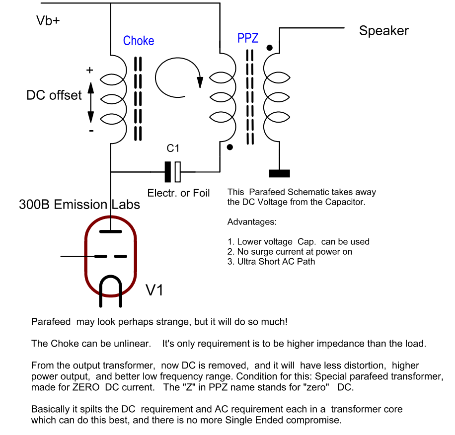
This is really the BEST. Period. Also least used, and least understood application. If you were think what is better, Push Pull or Single Ended... have a look at the Parafeed principle. This combines the advantages of PP and SE. Though it works on one tube, it's no SE stage. The transformer is a PP type. Read also here.
The Parafeed connection scheme differs slightly from normal SE connection, because it grounds the driving winding at one end, vs connect it to the V+ with SE or PP. Please let us know if you need a parafeed connection for any of the transformers, we can add it to the table here.
Noise - some small notes
Tone transformers if used well, are the most ideal noise and microphonics eliminators which exist. If a tube amplifier is microphonic, wouldn't it be nice if tubes don't have this 'problem' and you can stop selecting and brand picking? Do you recognise this situation: You use a specific tube and it seems noisy. Replacements are noisy too. But, some other people, with say, this type is not noisy at all. So how come? Do they have different tubes? The answer is: No! They have an amplifier with a different, a better circuit design. Microphonics of the SAME tube can be more, or less in another amplifier. Try it, and you will agree. That tells, it has also to do with circuit design. Specially with tube pre-amps this is the #1 problem: A fully wrong design. Such benefit from a step down output transformer like no other. Please look at the Notes for a few unsorted hints and hopefully good ideas.
Tube microphonics. Any kind of tube noise, also hum and white noise, will be reduced SIGNIFICANTLY with a step down transformer. This is less known, and we can only wonder why people cause themselves such expensive trouble by having dealers select tubes for low microphonics, which is usually disappointing. Whereas a step down transformer will give a much larger improvement, and costs less than expensive selections or exclusive NOS tubes. The way a step down transformer reduces tube microphonics can not be explained here quickly, but we just mention this at some places here. If this is new to you, try to learn more about it. (Read the Notes).
Generally, the choice is first for output impedance you NEED, and then for the gain of the whole stage you NEED. If you don't know these things, nobody can choose a transformer. Well you can, but the choice may be not good. So not first choose the tube, then choose a transformer to it, and then ask: What is the gain, ignore output impedance, and find out afterwards if you have an issue with microphonics or not. Like the doctor says, first the diagnosis, then the treatment.
Windings in series or in parallel? By connecting all windings in parallel, 1+1+1+1 winding comes out as just 1. By connecting all these windings all in series, it comes out as 4, and a series parallel combination gives 2. So that is three options. At the other side of the transformer, the same can be done with the windings too. Suppose it's 2.25 + 2.25 as with the LL1660, in series this gives a factor 4.5, and in parallel 2.25. This gives by itself 3x2=6 step ratios. Then, these transformers may all be used reversed, giving us 12 ways in theory. There comes already some overlap, like reversing a 2 : 2.25 transformer to 2.25 to 2, is almost the same. Also, not each theoretical configuration is a good one in practice. Like for a high impedance tube, low capacitance is important, which can be achieved by putting windings in series, but low impedance tubes draw a lot of current, which can be done by putting the windings in parallel. To make this choice easier, there are several good connections schemes in each data sheet, and the all refer to a certain driver tube impedance, and DC current if Single Ended. In many cases this is good start, but feel free to design your own schematic. In the table below here, you can find some which are not in the data sheet, and these are named J1, J2, etc.
All together, there is almost nothing you can not do with this transformer family. Frequency range and maximum voltage swing is very high. The many use options makes these difficult to wire it quickly. Some are to drive a transformer with a low gain tube, some for a medium gain tube, and some are for line Out applications, and will GREATLY reduce tube hum and tube microphonics. (See: the Notes for this). Moreover, they are PCB type, and you will need to solder wires to the PCB pins. I have been puzzling to find some intelligent PCB, but that ends up with either a PCB for each transformer and still limited possibilities. So I had the idea to use a matrix with solder bridges, and now we can simply connect any pin to any other. Like in the data sheets, or by any new ideas, and new transformers too.
Any new scheme of yourself, such are definitely possible. If you have tested it, let me know, and we can a programming for it.
Board removal. The board holes are through plated, but there are no solder islands on the back side. This makes re-wiring easy, and also makes board removal possible with a good desoldering tool.
Notes:
- New Configurations. The words of Per Lundahl: "New schemes can and will be found!" Such configurations are not in the data sheet. We use numbers here like ALT-X1, ALT-X2, etc.
- LL1667-1668 Parallel connected. Basically this changes 5mA version into 10mA version, at regular inductance, same as 10mA Version has. However maximum AC peak is only 50%. For that copper resistance is only 1/4. This option is very good, when you have maximum 195V RMS for LL1667, or less than 117V RMS for LL1668.
- LL1660S vs. LL1660. The S (screened) Series transformers are internally wired differently. Though every 'ALT', of 'S' and 'none-S' can be converted to each other, you can not just take the connections of an 'S' und use it for 'none-S', or vice versa. Please ask if some nice configuration is missing, we can just add it on this page.
- ALT-J1, ALT-J2, etc. These are alternative connections, which are not in the data sheet.
- Use of LL1660 as anode choke. This works very nice. DC current and inductance need a little calculation, and the formula is given for in the table. The intention is here, to use such a choke as anode choke, when you have it laying around anyway.
- Parafeed.
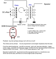 The inventor of parafeed is unknown, but Lynn Olson found a very old Western Electric schematics, using it for the first time. So it may perhaps have been a person at Western Electric. According to Roger Modjeski, a master circuit designer, parafeed is the probably the best SE circuit. PP-Z Series transformers are used for this. Here is the PARAFEED Schematic to use with the programming above. Parafeed requires an application note for itself, and can not explained here in detail in a just few lines. Basically, the signal is split in it's AC part and DC part, and then each is given to it's own inductor. Like this, the DC part can be handles by a plain choke, which does not have to be very linear. All it has to do is be a high impedance, no more. The AC part can be picked up from there, with a transformer which is made for DC free operation. So there has to be no air gap. Such can be a lot smaller, and rewards the user still with much more inductance, and yet much lower capacitance. Effectively, the transformer works better, and due to it's smaller size, costs less. The costs of having to use the extra choke are made by by this in total, because to the choke are little requirements. Even so, the more difficult to use AMORPHOUS cores work excellent with Parafeed, because with SE amorphous we must always try to keep the DC load low. Yet, with PPZ, the DC current is zero. The only drawback is, people don't understand so quickly the virtue of parafeed, and some mistakenly think, one BIG SE transformer costs less than a small PPZ transformer plus a simple choke.
Headphone Impedance. For this, we specifically recommend such with a high step down ratio. This reduces tube noise the best way. Electrical output impedance is calculated as: Rp/n^2. For instance with a tube of 1500 Ohms Rp, and step ratio (n) =9, we get 18.5 Ohms. The head phone impedance should have 3...9x this value, so here 56...167 Ohms. Any other headphone impedance can be achieved with the SAME transformer and the same tube. Like program the EE27 for a factor 4.5 would give 220...670 Ohms. Using a tube with another Rp as 1500 Ohms, would give different values of course. As this is difficult to predict on paper, it is really recommended to use the EE27 board and try out all three options, to decide what sounds best with the headphone of your choice.
- Shielded (S) Version. These transformers have another pin lay out by Lundahl. It means in the data sheet these have their own 'Alt' connection schemes. Though these schemes effectively do the same, they use another Index letter, to prevent mistakes.
- RCA Connection. If a transformer output is connected to a grounded RCA connector, Signal 'Plus' is connected to the RCA center, and Signal 'Minus' is grounded at, or near this connector. 'Plus' and 'Minus' are mildly twisted. Shielded cable is not needed.
- XLR connectors.
- FAKE XLR. This is not nice, but some 'so called' Hi-fi companies fool you with that. Signal is on XLR2 only. XLR-3 is dead, and connected to ground. Really, this is fake. So they show you a balanced XLR connector at the outside, but at the inside, a normal single wire is attached, and XLR-3 is grounded, instead of providing the balanced signal. Shame on them!
- Tube Microphonics is a difficult subject. These 20 lines here can not explain everything, but when this is new to you, try to do some of the calculations examples yourself. So what Signal (S) which goes into the tube stage? What is the Noise (N) added by the tube itself? What is the Signal to Noise Ratio (SNR) using a step down transformer, or not using it. If you understand the calculations, it will open your eyes for this subject. The MOST important thing is, never spoil your signal to noise ratio, as this is a thing you can never correct any more. So if a tube appears microphonic, you can call it a bad tube, or a bad circuit design. This gets almost always confirmed, if one angry customer 'can not use' a so called bad NOS tube, and sends it back. Then, the next owner may as well be totally happy with it, just because he has another, better amplifier. Most of the mistakes with microphonics are made with low level design of the amplifier, and really not with low tube quality. But we all know, in the end there is little other choice, as to do tube rolling, and it will help only a little bit. But what really helps very much, is not use a bad circuit design in the first place. In short, when there IS microphonics, you already HAVE a bad circuit design. With this I mean not how the amplifier looks from the outside, or what brand it is printed on it. Quality is something at the inside, not at the outside. It becomes visible only, when we look at the schematic. There is no other way to judge it. All those 'secret' schematics, don't let them fool you with that. There is no secret schematic, ever since the last patent on amplifier design, by Julius Futterman, who patented the OTL circuit in the 1953. Microphonics appear when you pass a small signal through a tube, which is capable of a lot more. (for instance 100x more signal). So the same tube, now driving an attenuating Inter Stage or attenuating output transformer, will now be running at accordingly higher signal, in the same ratio as the transformer attenuation factor. You will see the pieces fit together, when a typical pre-amp output transformer is LL1689, which has maximum 18x attenuation. 1/18 is 5.5%. Meaning only 5.5% of the original microphonics is left. So, tube microphonics may go from 'smallest chassis noise audible' to 'almost inaudible, even when you tap on the tube itself'. The question remaining is not really where you get the extra signal from, to drive the transformer with 18x more signal as before. All tubes amplify anyway, and all pre-amps amplify much to much anyway. So even now, the volume control works as it should again. Which is maximum volume at maximum setting. Also the factor 18 reduces output impedance with a factor 18x18=324. So you get an incredible low output impedance of such a pre amp, which is so low, you can move the volume control from the input, to the output, where is belongs with a professional design. Driving a 600 Ohms wire wound pot meter with it. And no, wires of a wire wound potentiometer have no 'sound'. What does have a sound is a scratchy carbon pot meter at the input. Such a wire wound pot meter functions comparable to an auto transformer output. Via a few hundred wires, it switches the volume levels from one wire to the next. You will not 'hear' these small steps, as you can with an auto transformer. These make often too large steps. Also, same as with an auto transformer, impedance and noise go down at lower volume, which is of course extremely beneficial, coming on top of the noise reduction we had already. Many times, after explaining this, people react fully confused, saying: Yes, but .... then I have a wire wound volume control at the output! Somehow they do not like those. Then if I ask, what advantage they expect from a carbon potmeter at the input, they do not know. Well, I also do not know.
- Step down is useful when you have enough gain. This lowers output impedance, and any kind of tube noise, incl. microphonics. Read also notes about tube microphonics.
- Step up transformers are ideal when there is not enough overall gain. A driver tube for this, should be medium or low impedance. Or even more, for typical low gain, low impedance tubes, like 45, 2A3 or 300B, if used to drive a step up Inter Stage, this is a near perfect concept. A Step-Up Inter Stage lowers overall noise of the whole amplifier significantly, when this method leads to elimination of one tube stage. If just not enough gain this way, consider in addition to add a step up input transformer. Ideally programmable EE20 board, with LL1545 or LL1544, because it can select a whole range of gain. Like this, you can choose the input gain you need. By all means you will increase the overall noise of an amplifier with a step up input transformer. So not only use it when there is lack of gain, but also it will reduce overall noise.
- Overall Noise of the amplifier has always to do with not destroying the signal to noise ratio (SNR). This includes microphonics. Once SNR is destroyed, you can not recover it. This happens when passing a small signal through a noisy or microphonic tube. Pass a HIGH signal through the same a tube, and it will add only very little noise. So work always with higher signal. Of course, when this HIGHER signal has to come from an additional tube stage, you will not achieve a noise reduction, but increase overall noise of the whole amplifier. Consider for that reason always an input transformer if you can afford it. So you go into the amplifier, and create directly after the input, 2x or 4x Gain with a transformer. This gain you get free of noise, at the small cost of a transformer. Then, in some cases it can eliminate one tube stage (Take the most microphonic stage for that). Consider in addition a step-down Inter Stage, if the input transformer gives more overall gain as needed. That means ANOTHER noise reduction, and the situation improves another step. By doing these things right, an amplifier can be made which is dead-silent and has no microphonics. Whereas the same tubes, would give microphonics in an amplifier without the right circuit concept, and people blame it on the tubes.
- Desoldering the board. Lundahl transformers officially are not made for desoldering actions. Specially with such desoldering tools with a spring inside, you can damage the pins. I recommend desoldering litz. If you are careful, I think it can be done. Though the board itself is double sided, we made the solder islands for the transformer and cables single sided, and a little bit too large hole diameter too. This makes desoldering a lot easier to do.
- Termination resistor, or Termination RC network. With all tone transformers, the high frequency range ends somewhere, outside the audible range. It ends with a normal roll off, when the transformer has a minimum load. Without load however, the signal may swing up, before the roll off appears, this is called ringing or resonance. This is a normal resonance with inductance and capacitance. It appears rather when the transformer is driven with a very low impedance, and when the signal is stepped up (more windings). If this appears so, either leave it as is, because this happens outside the audible range anyway. Or, this can be removed, if wanted, by adding a secondary load. The best place for such a load is at the transformer itself. For this purpose, the terminals Z1 and Z2 can be used to connect such a load. In some data sheets, a load value is recommended, either as Resistor, or as RC network. Before doing so, consider if it is necessary at all, by inspecting the signal with an oscilloscope, and drive the transformer with a 5kHz square wave. If there is no ringing (very short resonance) at the edges, nothing needs to be done. Another measurement method is, increase the oscillator frequency, and it can be seen if the signal swings up at a specific (resonance) frequency, before roll off begins. If this is the case, this can be damped by a load. If it does not swing up more than 30%, nothing needs to be done.
- Board Positioning for LL1667 and LL1668. The EE27 boards cannot be soldered incorrectly to the transformers, except for the Anode Chokes (LL1667 and LL1668). Always mount these with the text facing upright to ensure the correct orientation.
- Balancing the XLR Output with Termination Resistors. In some configurations, all output windings are connected in parallel. This results in a low internal resistance, which works very well when driving a grounded RCA output. However, when driving a balanced XLR output, there is no center tap available. You can easily create one by adding two 2k2 balancing resistors: One resistor between Z1 and L2, Another between Z2 and L2. With the correct solder bridge configuration (add bridge #1), the midpoint of these two resistors will appear at L1. Connect L1 to XLR1 (Ground) on the XLR connector. This will create a balanced output — so when XLR2 goes positive relative to ground, XLR3 goes negative. These resistors don’t need to have a very low value, as they do not carry any significant current. Their purpose is only to provide a small, symmetrical load on the differential output signal, which can actually improve performance in many cases.
- LL2766 Transformer. This is a classic and still highly recommended older type transformer. However, note that its pin layout is inverted compared to the other models. While the EE27 board still fits correctly, it will be rotated 180° due to this difference.
This transformer uses thicker output wire to achieve lower DC resistance, making it suitable for loudspeaker applications. - Reversed application, and DC Current Considerations. These transformers do not have fixed primary or secondary windings. They are designed for flexible use — you can configure them in whichever way best suits your application. This versatile approach is also recommended by Lundahl. However, there are some important implications for DC current handling, depending on how the windings are connected. In the data sheet, you will find two groups of windings: One group is labeled A, B, A, B. Another is labeled C and D. The maximum specified DC current applies to the A/B windings as shown in the data sheet. If a transformer is rated for 10mA DC current, and all A/B windings are connected in series, the total current rating remains 10mA. If instead, all four windings are connected in parallel, the effective DC current rating increases by a factor of four — in this example, 40 mA. When using windings C and D as a single-ended input, the maximum allowable DC current can be calculated, using the following relationship: I,max × 2, divided by the windings ratio. Thus 10mA × 2 divided by 2.25 = 17,7mA. This matches the example given in the LL1660 data sheet under configuration Alt. V, where the value is rounded to 18mA.
For users of Older Versions of the EE27 Board, we keep those pages online here: Version 1 and 2