Electron Engine ™
Printed Circuit Boards by Emissionlabs ®
EE21 Board, Several Configurations
- First Page
- Moving Coil
- Amplifier Input
- Parafeed Pre-Amplifier Output.
 Gain and Configuration (you are here)
- Testing, Tuning, and final choice.
- Some Applications
Configuration is done in this order:
1. Setting the gain (or attenuation) of the board.
This is done by connecting the transformer windings another way. This board has three possibilities for this:
 Option1. Solder Bridges. This doesn't need the DIP switch (Piano Switch) or the external switch. If the gain is fixed, or needs hardly ever changed, this is the way.
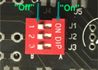 Option2. DIP Switch. If you need to do some testing, without using a solder iron.
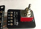 Option3. External Switch. This E22 board is connected via wires to the EE21 board. The gain can be changed at any time between the two possibilities if each transformer.
- Low Gain (or low attenuation) use J2, or J5, or the 'High' position of the flip switch.
- High Gain (or high attenuation) use J1 + J3, or J4 + J6, or the 'High' position of the flip switch
Transformer |
Gain |
Termination | |
1x |
R1=10k, R2=47k | ||
0.5x |
R1=10k, R2=47k | ||
4x |
R1=47k, R2=220k | ||
8x |
R1=47k, R2=220k | ||
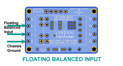
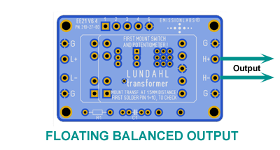
Now the board already works! Signal is connected "floating" to H+ and H- and L+ and L-. Another word for floating is: balanced.
If a floating input or output is really needed, leave it like this. In many cases however an unbalanced (RCA (Cinch)) signal is needed, or a centered signal.
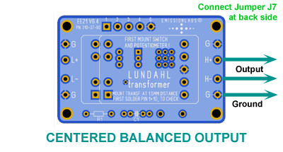
2. Configure the input and output for unbalanced, balanced, or balanced-centered
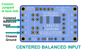
A Centered signal means we use a winding with a center tap, and this center tap is grounded. This enforces a ground reference to a balanced signal, and hum rejection becomes so good, that for aux connections, you could work with just a twisted wire pair, so an unshielded cable. Provided, at the L-Side, the windings are in series, the solder bridge for centering this side becomes effective. This would be the Low Gain choice.
- J7 centers the L-Side (See above text)
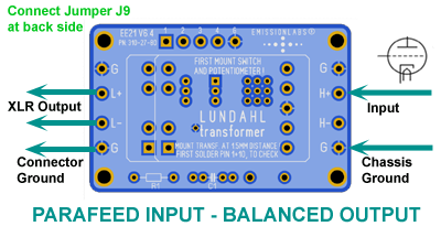
- J9 centers the H-Side, and works always.
Use of the G-Connections
G means just Ground, and these are all connected to the board ground plane. Yet these can do a lot.
- A fully floating balanced connection will probably work, but is not a good idea still. Better is to use a cable shield, and connect this shield to G. Like XLR Connectors are doing.
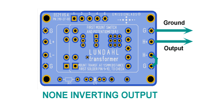
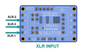
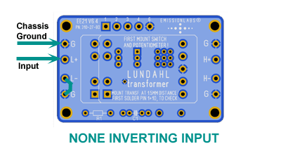
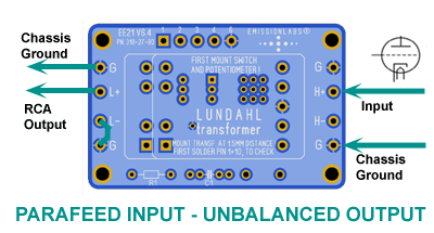
- If L- is is connected to G, the L+ becomes an unbalanced (RCA (Cinch)) input, of a step up transformer. The same applies for the H-Side. In the configuration pictures are many examples for this.
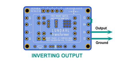
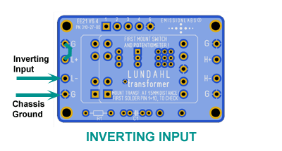
- From the above, when connecting H+ to G instead, the input becomes inverting. This is recommended when the whole amplifier is inverting, which is in fact a design mistake, but we see that often. So when adding a transformer with the EE21 board, we can elegantly fix this problem.
Choose a termination network if required for the application
Jumper J8, J10, J11. These are for tuning the EE21 board. Use the main pages for this (So "Moving Coil", etc at the top of this page)
Several Input configurations |
Several Output configurations |
 |
 |
 |
 |
 |
 |
 |
 |
 |
 |
 |
 |
Notes:
A Centered signal means we use a winding with a center tap, and this center tap is grounded. This enforces a ground reference to a balanced signal. This is very useful, because if this not done, so when connecting a floating output to a floating input, you can never tell the AC(hum) level with respect to case ground. To help understand this, imagine the sending winding is lifted up to a +100V DC level via the center tap. Then, then the receiving end would see this DC level also. Yet the transformers would still work normal, and have no effect from the +100V. In the same way, we could change this DC voltage to a negative voltage, because this does not change the differential signal either. But then we might change it faster, or connect just 50Hz 100V AC voltage to the center tap. Even this would have (almost...) no effect for the same reasons. However there will be a very small effect, due to AC parasitic coupling from winding to winding. In engineering such an AC signal is called a common mode signal, it's an unwanted signal. It is the opposite of a differential signal which is the intended signal. Common mode rejection of a balanced input is very high, but not endlessly high, and in some situaions it can become audible. Due to the fully double coil construction, Common Mode rejection is exceptionally high with all Lundahl tone transformers, specially those with a static shield, will outdo any electronic solution by far. This described issue, is however the reason why either sending or receivung side should be used 'centered', just if we can do so with little effort. And many times we can.
In the above text, I mentioned 100V AC. Such an signal is present at the mains cables inside the walls of each house. The walls are internally wired with that like spaghett, and they work as a very good electrical field transmitter antenna. Most of all, because a floating transformer input has a very high impedance to ground, this electrical field can be picked up easily by the inter connect cable, and cause a remarkably high AC voltage, if totally inloaded.To prevent this, it is very efficient, to connect either the sending or receiving side with a center tap to ground.