Electron Engine ™
Printed Circuit Boards by Emissionlabs ®
EE21 Board, MC Applications
- Overview
 MC Applications (you are here)
- MC Tuning
- All Connection Schemes, Complete Overview
- Unsorted Application Information
Moving Coil
| Input | Gain Low |
Gain High |
Core | Characteristic |
| LL1681 | 8x |
16x |
Amorphous Iron | Studio Favorite. What goes in, it what comes out. |
| LL1931 | 8x |
16x |
Amorphous Cobalt | Best Sound of Amorphous, 6N 'Cardas' wire. |
| LL1933 | 8x |
16x |
Nickel | Clean sound, Low Distortion, 6N 'Cardas' wire. |
| LL1971 | 12x |
24x |
Amorphous Cobalt | Best Sound of Amorphous, 6N 'Cardas' wire. |
| LL1941 | 1:16 |
1:32 |
Amorphous Cobalt | Best Sound of Amorphous, 6N 'Cardas' wire. |
| LL1943 | 16x |
32x |
Nickel | Clean sound, Low Distortion, 6N 'Cardas' wire. |
Make a good beginning, to come to a good end!
The output signal of an MC is only 0.5mV. Then, if we say residual hum is 1%, this would be audible and nobody would accept it. Yet at 1% we talk about 0.005mV
Now it is not impossible to measure 0.005mV. A possible way would be, to take the speaker outputs which let us hear that hum, and measure it from there, knowing the total amplification of the amplifier. Yet at the mains frequency it becomes increasingly difficult since there is 230V electrical field radiation from the cabling of the house everywhere. This disturbs any measurement totally. So what you think you are measuring is very likely not what is taking place in reality. It is exactly this, what results in the well know situation: 'I tried everything, but I can not find the reason for the hum', and you get stuck at that point. For this reason, AVOIDING things which cause hum, is the better way to go. A hum free amplifier is the result of the right concept from the beginning. It will harldy result from an unclean concept, and then tweak the hum away with some tricks. For this reason, we use PCBs with a 1/6 mm thick ground plane, not even thinking of the possibility to do it without. You can not compete against this with hand wiring.
Some tips and tricks.
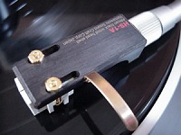
The EE21 board should be placed close to it's signal source. When possible, lay the wiring on the metal of the chassis, because electric and magnetic hum fields are lowest there. Keep the wiring minimum 10cm away from mains transformers, power supply parts, and cabling to those.
For unbalanced inputs, if inside a metal cage, shielding is not needed when the cage is a dedicated MC box only. Using a wooden case is also possible, but then coaxial cable should be used. If inside an amplifier, unbalanced MC inputs should have shielded cable, and balanced inputs should have drilled wires.
If in a metal housing, the EE21 board is grounded via the screw holes, but do not trust these to give a good connection for ever. For some reason I don't know, PCB screws always get a bit loose over the years. For this reason, use a soldered wire in addition, via one of the 'G' connections. Since this wire is a potential ground loop, mount it close to the PCB.
Moving Coil, Grounded Type RCA (Cinch) Connector
not recommended
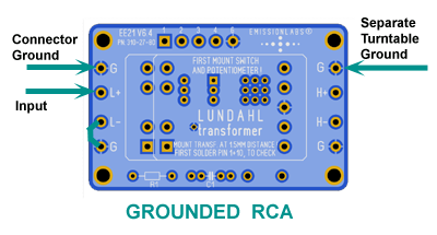
We often see people use this wiring satisfactory. Yet, there is a ground loop, and hum may occur just by reversing a mains connector, some changes at the cables, or other unexpected reasons.
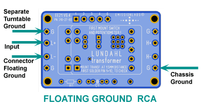
An floating ground RCA (Cinch) connector has a balanced input, and the turntable chassis serves as ground reference.
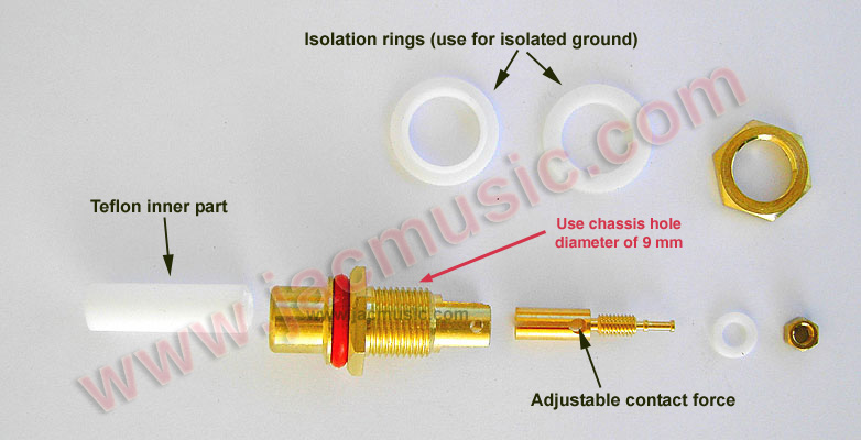
This is an isolated ground RCA (Cinch) Connector by Yamamoto Soundcraft Japan. This preserves the balanced character of the transformer input.
Connect L+ and L- directly to the RCA (Cinch) plug, Since the board is now floating, it needs a ground reference. One of the 'G' connections is attached to the chassis.
 Turntable ground. There is normally a screw or a connector, for chassis ground of the turntable. Through this wire flows no current, but it prevents a voltage difference between turntable chassis and the chassis of the next device in the chain. This is connected with just a loose wire to the device where the MC transformer is mounted. If this is a wooden box, it still needs a connection! This is screw connector or banana plug, which internally gets connected to the ground plane, 'G' of the EE21 Board. If the MC transformer is in a metal housing, this wire is connected this wire to the metal. WIth a wooden MC box, the 'G' is of course connected to the output in whatever way it is done, and so the ground references of the record player is passed on to the RIAA amplifier metal housing.
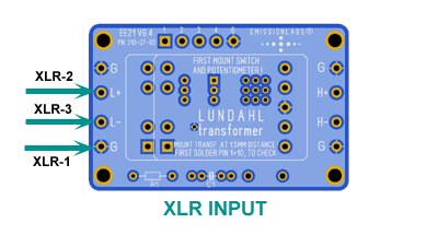
An XLR input works almost the same like the above floating ground RCA connector, but an XLR cable is better balanced, and the cable shield is not used for signal, but only for shielding. So any hum current trough the shield can not generate electric signal, which is what makes XLR better. Such current may sometimes exist, because we connect two apparatus with each other via the ground of the cable. That is the reason for using XLR, and such current doesn't matter.
Turntable ground. This is by definition connected to the XLR cable shield inside the turntable, at XLR-1. The manufacturer already did so. A loose wire from the turn table may be connected still as additional security, and the idea is that the ideal ground connection is not 'plugged' but 'screwed'.
The XLR cable shield coming from the turn table, one way or another needs to be connected to RIAA amplifier Chassis. If we use a wooden MC box, it is passed on via the EE21 board. So, at the output side, the 'G' is connected to XLR-1, and the outgoing XLR cable will make the connection to the RIAA amplifier chassis. With a metal MC box, it works the same, but the metal of the box becomes part of it.
If the EE21 board is build into an amplifier, it is best to ground the XLR-1 directly at the connector inputs.
Gain Selection
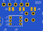 Gain can be choosen from two variations. Choose to use solder Jumpers (J4...J5) or the piano switch J1...3. Or use an external switch, connected to the board. Introduction and gain setting
Part2. Damping of the Cartridge
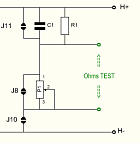 This comes all in the end as a final adjustment. First the board has to be set up and make it work. Then, electrical damping of the cartridge can be adjusted. The cartridge is already damped more or less correct by the load of the phono amplifier. Yet not extremely perfect. So fine tuning is a good thing to do, when everything is finished and working. Read more about this