Electron Engine ™
Printed Circuit Boards by Emissionlabs ®
EE21 Board, Some unsorted Applications
- Overview
- MC Applications
- Amplifier Input Applications
- Amplifier Output Applications
- All Connection Schemes, Complete Overview
 Some unsorted Application Information (you are here)
Inverted or None-inverted signal?
An amplifier should not invert the signal! Unfortunately amplifier manufacturers pay seldom attention to this. However an inverting amplifier can cause instability problems. After all, an oscillator is nothing but an inverting amplifier with the output connected to the input. Perhaps you had sometimes the situation, pulling out the input cable from a switched on amplifier, and that moment it responds very shortly with a distorted, screaming sound at full loudness. When you have bad luck, it kills a tweeter. That was is an inverting amplifier!
So in case an input transformer is used anyway, we have the options open again. CHECK if the amplifier perhaps inverts the signal. If so, phase reversal at the transformer can elegantly correct this. More information about this.
Creating an BALANCED input with an RCA (Cinch) Input
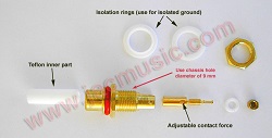 I recommend this as a standard for tube amplifiers, using the RCA (Cinch) input for this. Like this it becomes compatible with all existing equipment. Yet, it gives the advantage of a hum-free, balanced input. More information about this. For this however, an isolated ground type RCA (Cinch) connector has to be used, such as the Yamamoto.
Hint: When connecting a balanced RCA (Cinch) connector, even an XLR connector can be connected in parallel to it.
Push Pull amplifier, Phase Splitter.
When constructing a Push Pull amplifier, additional circuitry is needed to generate the reverse phase for one half of the output stage. An input transformer can change a 1V input signal, directly in two signals of 2...4V, with 180° phase shift.
Fake XLR inputs
This is a bad one. Yes, several amplifiers have fake XLR inputs. It is clear why they do this, because a real (balanced) XLR input requires a lot of electronice, or a transformer. Since buyers e are happy to see those professional inputs, fakers buy a 1$ XLR connector from China to make it look better from the outside. Internally, they just dump one line of the balanced signal into a resistor, even faking a load. So from the outside it looks real, you can not see it, or measure it. In reality, they convert the balanced signal into unbalanced. It's as fake as can be. So people pay the extra price for a (real) top class pre-amplifier with (real) XLR outputs, and connect it to the (fake) XLR inputs of the speaker amplifier, thinking it is better. This a plain fraud, but please regard this my personal opinion only. Why I bring this up here? The situation is however, such an amplifier has already the XLR connectors mounted. So specially here, using the EE21 board for instance with LL1588 or LL1676 in 1:1 configuration is the BEST you can do. Or, you can save some money and space, and use the tiny EE31 board, which is very basic and also does what it has to do.
Some Applications
- Application with LL1588
- Application with LL1922
- Application with LL1674, LL1676
- Application with LL1592
1) Application with LL1588
This is the neutral transformer, giving a gain of 1x or 0.5x. Yet by reversing the board, a gain of 2x can be achieved also. So buying the EE21 with 1588 gives three options.
In case you have chosen LL1588 for a 1:1 application, and you find out after all, some GAIN would have been better, here is an unspecified use, but it will work, and give a gain of 2x. Close only Jumper J2, and leave all other jumpers open. Now REVERSE the EE21 board, like below, and you will have a gain of 2x. I have not tested this, but I see no reason why it will not work. More information here.
2) Application with LL1922
This is transformer for creating gain of 4x or 8x.
A transformer creates gain free of any noise and hum, and a distortion level better than any tube. Also if a driver stage has 'almost' the required gain, do not add another tube stage, and get stuck with too much gain and noise. Just add a step up transformer!
The drawback of a step up transformer is it's relatively low input impedance, in the range of a few kOhms. Yet, today we do not have the 1940's requirement any more where an amplifier had to be 47k in order to be an optimized load for a crystal record player. (Yes that's where the 47k came from, long ago). So when the source can easily drive 2k, which is today totally normal, why not use a step up transformer, and get noise free gain + a balanced input?!
3) Application with LL1674 and LL1676
These are two very classical Lundahl transformers for impedance matching, or a 1:1 47k input with the LL1976. Used by many. Both have a core of amorphous iron.
Basically LL1974 is medium impedance, and LL1976 is high impedance, but here again the EE21 board offers some additional variations.
Gain |
Termination | Jumpers | ||
Single Output, impedance matching No Parts mounted. |
4x |
600 Ohms in, 10k Out. (Can be reversed) | J1 + J3, or J4 + J5 |
|
Phase Splitter Output No Parts mounted. |
4x |
Source must be 150 Ohms | J1 + J3, or J4 + J5. And J6 |
|
High Impedance (47k) input No Variable Resistor mounted. |
1x |
R1=33k | J1 + J3, or J4 + J5 |
|
High Impedance (47k) input |
1x |
R1=4k7, P1=100k, adjust P1 for best square wave response | J1 + J3, or J4 + J5 And J10, J11 |
|
Medium Impedance (10k) input No Variable Resistor mounted. |
2x |
R1=68k | J2 or J5 J8, J10 |
|
Medium Impedance (10k) input |
2x |
R1=10k, P1=220k, adjust P1 for best square wave response | J2 or J5 And J10, J11 |
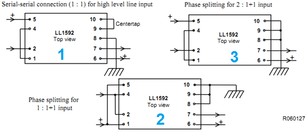
4) Application with LL1592
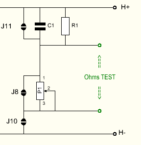
This transformer will go up to 100kHz with the RC network for tuning. The EE21 Board has this option
Gain |
Comment | Termination | Jumpers | |
1x |
Drawing #1 (above) Connect G to Ground |
R1=6k8, C1=390pF | J2 or J5 |
|
| 1x | Drawing #2 (above) Connect G to Ground |
R1=6k8, C1=390pF | J1 + J3 or J4 +J6 And J8, J7, J10 |
|
| LL1592 | 0.5x | Drawing #3 (above) |
R1=6k8, C1=390pF | J2 or J5 |
| LL1592 | 2x | Unbalanced Amplifier input with 2x Gain Connect to Ground: L-, H-, G. |
R1=6k8, C1=390pF | J2 or J5 |
| LL1592 | 2x | Balanced Amplifier input with 2x Gain Connect to Ground: H-, G. |
R1=6k8, C1=390pF | J2 or J5 |