Electron Engine „˘
Printed Circuit Boards by Emissionlabs
- Introduction.
- Use of Triode Board (EE12) with Power Supply EE11
- Use of Triode Board (EE12) with external Tube Tester
- Tube Data Table
- Typical Test sequence
- About the purpose of burn in.
- Fusing of the boards.
 Building instructions (You are here)
- Options and Support
- Fault Finding
Building Instructions.
Power Supply EE11 (V2.3 / 2.4) with Socket Board EE12 (V2.7).
We supply only the parts. The PCBs are not intended to use without a safe housing.
Burning in with AC or DC voltages.
It is hard to say, what is better, burn in with AC or DC. For this reason, the Version V3 now has the option to add DC testing to it, later. This is explained under Options. Initially the burn in device should be build for AC testing. Though we call it AC testing, it us in fact rectified AC voltage, we use a similar method for this, as in the famous AVO tube testers. When going to DC testing as an option perhaps later, you will see it works the same, but DC testing is more gentle to the tubes, because the signal has no current peaks. However there are different opinions about what is better. So we have now both options with the version V3.
Cooling
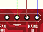
The housing needs sufficient air flow, because depending on the number of Socket Boards EE12, the number of plugged tubes, and their type, close to 175 Watt heat may be generated under maximum conditions. However when burning only 10 tubes of smaller type, such as ECC83, heat generation is relatively low. In many cases a fan will not be needed, because the heat in the tubes is what we actually want. When constructing a closed housing, it is a good idea however, to prepare the position of a fan, in case you decide to use it later. The power supply board has prepared output connections for a FAN already. This fan must be an AC type, it works on the MAINS VOLTAGE.


At the beginning:
- The EE12 Socket boards and Power Supply EE11 must be in the same, metal housing, to prevent oscillations, caused by long wires, and strange wiring concepts.
- Use the empty PCB's to pencil the position of the mounting holes on the chassis.
- Wires are not supplied with the kit, but make sure the cabling of the High voltage parts can withstand 230Volts AC and 350V DC.
- For using three EE12 boards, the cabling of the heater (Terminal K and L) must be 6 Ampere as a MINIMUM. Have a look at the transformer wire, going into the power supply board, to see what kind of wire that is. Such a wire you need to use. Reason to use thick cable is: When you have a heater short, and the cables are too thin, it would not burn out the mains fuse. (Which would damage the too thin cables)
- The ground wire carries little current, but should be a fat wire too, so they provide a good signal reference.
- Colors: It is strongly recommended to use the wire colors of the schematic. For failure finding or repair that is better, if it corresponds with the documentation here.
- The unit should be build directly into the final, metal housing. Use no wooden or plastic housing.
- The power supply board is also the interconnection board. You will see this when you build it, and it becomes no mess. Once the power supply board, and the switches are build inside the housing, there will be little cabling left and the Power Supply EE11 can already be initially tested without Socket Board EE12 attached to it.
- After the Power Supply works, the first Socket Board can be connected, after this was tested and calibrated before. This testing of the Socket Board EE12 is done with the board fully separated from the burn in device. When you have one socket board EE12 ready and tested, attach it to tester, and have the tester work for the first time. (follow the test sequence as recommended). Prepare the other EE12 boards the same way.
- Mount the Socket Boards EE12 such that you can flip them over to the right side, to work on their bottom if needed. For this purpose, all cables are on the right side. Each Socket Board EE12 has also connections for the next socket board, and a maximum of three boards can be connected this way.
Good Grounding Practices
Keep SAFETY Ground apart from SIGNAL ground. Safety ground has it's own wiring, preferably yellow-green. Signal ground is black. Though safety ground and signal ground are electrically connected to each other, their paths are separated, which works out in case of a short to ground.
A closed metal chassis should be used, for electrical safety. This chassis is not supplied. So the open construction, here on the website, shows the only the construction without such a metal cover. A mains inlet plug should be used, because this reduces the risk of wiring errors, at critical place. So do not feed a mains cable through a hole.
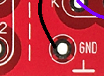
The Power Supply and the Socket Board, and socket board deck plate, have GROUNDED screw holes, these should all be electrically connected to the metal chassis. A multiple grounding is safe and it prevents RF oscillation. Remove any paint of the metal chassis if there is some
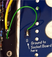 To the Socket Board EE12 belongs a cover plate, which must be connected with a ground lead to the board itself. Though the cover plate is painted blue, it has a copper surface at both sides, which is grounded to the screw holes. Also a ground connection is made to it with a wire. (See the picture) Yes, I need to replace this with a yellow-green wire, I know.
1) The mains cabling
- Safety regulations in all countries say, a safety ground connection must be made to the chassis with a copper screw, with a shortest possible cable, close to the mains inlet plug. This screw may only be used to ground the mains inlet plug, and the SAFETY Ground of the electronics. So two wires are attached there, and no more. One is from Power Supply EE11, where the 'earth' symbol is. The other goes to the mains inlet ground.
- Right after the mains inlet plug comes a double pole mains switch, and from this switch the mains wiring goes to "Main-in" of the Power Supply EE11.
- Mount on the chassis: All switches, and the bias potentiometer.
 Example of Safety Ground symbol
 Example of Signal Ground symbol
2) Mechanical mounting of the Power Supply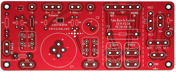
- Eight of the rectifier diodes are mounted upright. The cathode ring marking is on the PCB. Check this carefully.
- Close the jumper J1. This shorts the ampere meter even if you use one. Attach an ampere meter later, if you want so. First it should work without meter.
- R1 and R5, C1 and C2 are optional, and not used now.
- Mount all other electronic parts.
- Mount the board and the transformer on the chassis
3) Connect the transformer
The transformer is made in Europe. All wires go to the Power Supply EE11 .
Connect it as in the wiring diagram.
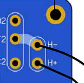
Though the tube heater inputs of the Power Supply EE11 are called H+ and H-, as well AC or DC voltage can be connected to it. In case of DC this is your own modification. In that case, plus and minus have to be wired correct. More information about this under Options.
4) After this is done, the Power Supply EE11 can already be initially tested.
- First, with the mains cable unplugged, check if the metal parts of the switches have zero ohms to the chassis. Any paint or non conductive clear coating, must be removed.
- Check if the mains entrance ground has zero ohms to the chassis.
- Check if the resistance between power Supply Board ground, and chassis ground is zero ohms.
- After switching on, on any terminals is high voltage!
- ALL VOLTAGES are tested with a normal multi meter.
- The board has an output to switch a fan. Even when not using this, this output can be used to check the mains is wired correct. Switching on and off the mains, must give the mains voltage on the fan output. (So 230V or 115V, depending on your country). Check the fuses, if this is not working.
- Between B- and Ground: -33V DC
- Between L and CT2: Appr 13V. AC
- Between UA and Ground: +300V DC
- If the above tests are passed, continue with the next points. If not, first solve this.
5) Wire the switches, bias potmeter.
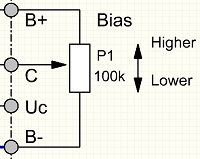 For potentiometers, no standard numbering exists. Even the center tap is not always located in the middle. We do this another way: Set the potmeter somewhere in the middle, and find out which of the connections measure 100k resistance. The remaining connection is the center tap. With a pencil, write 'C' on it. Then, turn it all clockwise, and measure which side of the 100k is now connected to the center tap, that one is called 'B+'. The remaining one, write 'B-' on it. Now just connect it to the PCB like that.
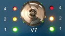
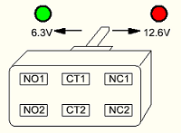 The switch for 6.3V / 12.6V is connected to the following terminals of the Power Supply EE11: NO1, CT1, NC1, NO2, CT2, NC2. This is a double switch, named S1 and S2. 'NO' means Normally Open, 'NC' means Normally Closed. 'CT' means Center. Mind the position of the Red and Green LED. The switch has screwed terminals, and the case is not very solder-proof plastic. If you are good at soldering, it may be possible to solder the wires to the switch quickly, without overheating the terminals.
 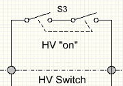 For the anode voltage (HV 'on') we recommend a double pole switch, for more safety.
6) Now the power supply EE11 can be further tested.
- Switch the mains on, but keep the anode voltage switch off.
- Between RG and L must be 13V.
- Set the switch to 6,3V. Now, between K and L must be 13V.
- Set the switch to 12.6V. Now, between K and GND must be 6.5V. Also between L and GND must be 6.5V.
- Test the control voltage on 'Uc' against ground. If the potentiometer is turned counterclockwise, the voltage at Uc is -33V DC against ground. If the voltage seems to rise and fall in the opposite direction as expected, the potentiometer was wired wrong by mistake. At this point (with Anode off) what only counts, if has to give -33V fully counterclockwise, and voltage becomes less negative if turned clockwise. If so, it is ok. Do not make the next step, if this is not working.
- Set the Anode Volt switch to "On". Now 'Uc' can vary from negative to positive voltage.
- If the bias is turned clockwise, the control voltage Uc becomes at first zero Volt, somewhere half way. If turned further, to maximum, the voltage becomes positive against ground. (See also the notes at the end of this page).
- Further testing will be with the Socket Board attached.
7) Building, Testing and calibrating the Socket Board EE12
- Building the Socket Board EE12 will take 2 hours. It needs a multi meter, and an adjustable power supply for testing and calibrating the LED indicators.
- If you have no adjustable DC power supply at hand, this part MAY be skipped, but an soldering error with so many LED mA indicators can be made, and testing is better.
- First apply the solder bridges V1...V10. These CONNECT each tube grid pair to the grid control voltage line (Uc) . Disconnecting is only needed in case if fault finding, which would then separate each tube from the rest of the circuit. Normally this is not needed to disconnect. So we connect them here all at once.
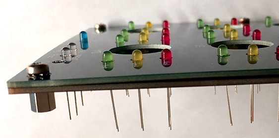
- Plug in all LEDs, not solder them yet. Provisionally screw the cover plate on the Socket Board EE12, to hold the LEDs in place. The Cathode is the SHORT wire of the LED, and the CATHODE comes into the SQUARE solder pad. Do not do this wrong, is would be extremely nasty to fix, when all LEDs are mounted wrong. Also, on LEDS there is a marking on the case, which is not always the cathode. Even so this may be random in one charge of LEDs. So only look at the shorter pin. Also from what you can see inside, the cathode can be recognized. The cathode is the metal cup you can see inside the LED.
- Do the soldering as follows, to prevent mistakes:
- When the board is like in the below picture, check once more, if all LEDS Cathodes are connected to the square pad. Then, cut off the LEDs wires, and solder only the cathodes. These 3mm LEDs are good quality, but still LEDs do not like very hot soldering. Use a solder with low temperature. Very little solder is needed, solder them quick. Do not solder the anodes yet. So all LEDS are now attached with only one wire.
 .
. - After having soldered one lead only, remove the cover plate , and check if the LEDs are nicely in rows and columns. They are still soldered now at only one side. Fine-correct the position if needed. Do not bend them heavily, because this can crack the plastic, and even though they work, such cracked LEDs may loose brightness later. Check again if the cover plate fits nicely and no LED is forced against the side. If all is ok, solder also the anodes. You need to treat LEDs always more careful than any other part. It is not allowed for commercial products, but good old lead solder is better for the LEDs. For private use, this is still allowed, and it is normally for sale.
- Process the resistors same way as the LEDs, with the cover plate keeping them in place. Insert all resistors of one value first. That prevents confusion. Resistors which have the same values are marked like: A, B, C, S. Be careful, the resistors are not positioned symmetrically on the right and left side of the board. Cut all wires off, then solder them all on one end only. Remove the cover plate, bend the resistors nicely in position, and then solder the other end.
- You will see, doing it like above, is almost no extra work, but optical result is much nicer.
- For soldering the socket, please read this text carefully, because you will plug and unplug tubes very many times. A bad soldered sockets is nasty, and would bend the tube pins. The Chinese sockets have the contacts much to loose inside the ceramic, but it's how they are. To deal with this, use an old tube and plug this into the socket before soldering it. Then solder the socket while the tube is inside. This aligns the contacts nicely opposite to the tube pins. First solder Pin1 and 5, and then check if the socket is positioned nicely horizontal. This is important, because later you can not correct this any more.
- Prepare the tube sockets after soldering. This needs some consideration. New tube sockets are too tight at first. This is normal, but we want to preserve the pin quality of the tubes we are testing. Stick a jewelers screwdriver with a shaft diameter of 1.15mm into each socket hole. (No larger diameter). This will widen the contacts a little bit. In case you widen it too much, with the same jewelers screwdriver you can make the contact tighter again. This is some extra work, but it pays off, and preserves the optical quality of the tube pins this way.
- Add all other parts (as in the links below).
- Position the miniature potentiometer on the socket board correct, look for the metal dot, and check if the screwdriver hole is nicely over it.
- Mount the grid and screen capacitors on the board. (These are 40 pcs 100nF capacitors)
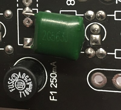
- Mount the precision melt fuse ("Littlefuse" Type), and the High Voltage RF blocking Capacitor at the bottom side of the board, (pic1) "Green Drop" type capacitor.
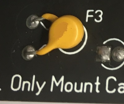
- Mount the two resetable thermo fuses at the back side of the board. (pic2)
8) Testing of the LED milliampere indicators:
The Socket Board EE12 has 20 indicators, for 1, 2 or 4mA.
- The mains is disconnected for this.
- Insert a small piece of blank wire into tube socket number1, to connect Pin8 with Pin3. Pin numbers are printed on the PCB.
- Connect an adjustable DC 0...15V power supply, with it's ground to 'GND' of the board, and the positive to the wire piece described above. Set the power supply to 0V first, this is important.
- Via the wire piece, both mA indicators (left and right) work now at the same time. In the next steps, check if these both work the same. If so, they work good.
- Begin with 0 Volts. Do not begin with 15 Volts, this may do damage otherwise.
1V: LEDs will be off
2V: Green LED begins to burns dim
3V...5V: Green LED burns bright.
Do NOT yet go above 5V. - If no LED burns now, the power supply may be connected wrong, or the LEDs are mounted wrong. DO not apply more than 5V if nothing works, because reverse voltage of more than 7V damages the LEDs!
6V: Yellow LED begins to burn
7..9V: Yellow LED burns bright
10V: Red LED begins to burn
11V: ...14V RED LED burns bright
15V: All LEDs burn bright.
- Check for good balance between left and right, all the way from 1...15V
- Repeat for each of the 10 sockets separately. Remember to start always at 0V. This is important.
9) More testing.
- Test for shorts. With no tubes inserted, all of the below must measure like an open connection:
* Ua to Ground
* Uc to Ground
* K to Ground
* L to Ground.
* Between Ua and Ua.
* Between Ua and K.
* Between Uc and K.
* Between K and L.
- Test the heater circuit. Insert two tubes from the testable tubes list, one tube in the socket V1, the other tube in the socket V6. (no other sockets). Measure the impedance between Terminals K and L. It should be close to a short now. Remove both tubes, it should be open now.
- First we connect only the heater supply of the Socket Board EE12, to the power supply EE11. This requires three wires: K, L, and GND.
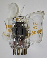
- Take one tube from the testable tubes list, which needs 12.6V. Insert it in socket 1, and it should glow at 12.6V, and glow very weak on 6.3V.
- Do not plug or unplug tubes with the mains on. This may cause damage. Switch the mains off, set the heater to 6.3V and insert two identical tubes from the testable tubes list, which needs 6.3V, by this list. Insert those in sockets 1 and 6. Switch on, and the tubes should glow normal now. Repeat for socket 2+7, 3+8. 4+9 and 5+10. Always insert an EVEN number of 6.3V tubes of the same kind, and always two in a row. (With 12.6V tubes this is not necessary, these can be placed anywhere).
- Reminder: Do not plug or unplug tubes with the mains on. This may cause damage.
- After these tests are passed, all heaters work good.
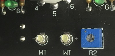
10) Calibrating the white 'GRID FAULT' LEDs.
There are two LEDs, one for positive grid (fault) current and one for negative grid (fault) current. For fault current, we define positive grid current as electrical current coming FROM the tube. The negative LED burns when current is in the other direction, so into the tube. These LEDs measure a threshold. So below 1mA they are off. Above 1mA they become suddenly very bright. These LEDs will burn out in case of Anode to Grid short, thus protecting the rest of the circuit (So become 'open') Such a short is really extremely rare, and for the very unlikely case it happens, and with a full short, you need to replace the white LEDs. These LEDS are uncritical, any pair of white LEDs will work. This method, using the grid current LEDs as a fuse, I have copied from the Hickok tube testers, where they do the same thing with a small light bulb. It may seem strange, but LEDs are very reliable fuses. At common faults, like grid to cathode short, at gas, or simply too high bias, the LEDs will burn, but not damage. In case one white LED is damaged, you need to replace both with white LEDs of the same manufacturer, and re-calibrate the circuit for the new LEDs.
CALIBRATION of the grid fault indicator at 1mA.
- The power supply is disconnected from the mains, and the Uc wire is disconnected from the power supply board.
- Initially set the calibration potentiometer in the middle. Connect the POSITIVE of an adjustable power supply, via a resistor of 2k7, and via a milliampere meter to the Uc wire. The NEGATIVE is connected to Pin7 of socket 5 with a piece of blank wire, you stick into the socket.
- Raise the power supply from 0 to 5V, and at some point, with the calibration potentiometer, it should be possible to change the LED brightness. This proves only this LED is working.
- Now REVERSE the power supply connections. Now the other LED must burn the same way. This proves only this other LED is also working
- Keep the power supply connected like this, but set it to zero Volts.
- For calibration, set the potmeter roughly in the middle. Now increase the power supply voltage until 1mA is indicated by the multi meter. In this condition, set the calibration potmeter such that at a power supply voltage change, the LED will begin to burn at 1mA. (So the power supply VOLTAGE is not important for this, calibration is only by the CURRENT)
- After calibration, the LEDs are threshold indicators, which are off below 1mA, and above 1mA they increase brightness very rapidly at higher current. By itself the brightness is not what we want to judge, it is only the "off" threshold which we want to look at, later.
- Connect the Uc wire again, and the calibration is done. This must be done separately for each EE12 board, if you use more than one. .
P-e-r-f-e-c-t. You made it until here :)
This is good, because from now on there is very little which can be wrong now.
11) Initial real testing, combined with the Power Supply EE11
- No tubes inserted, Mains off.
- IMPORTANT: Close all solder bridges V1....V10 on the EE12 Board. Do not forget this! These are only opened for fault finding.
- Connect Ua and Uc of the power supply to the Socket Board EE12.
- Anode off, Bias potentiometer of EE11 roughly in the middle. (so 5 turns)
- Switch mains on. Switch between 6.3V and 12.6V. Green and Red LEDs must indicate Green = 6.3V, Red=12.6V. If not, go to the fault finding section.
- Assuming all things work so far: Switch Anode 'on'. Blue Hazard LED must burn. If the LED stays off, go to the fault finding section.
- If the above works, set bias to minimum. Turn the knob all the way, counter clockwise. Check if this gives appr -31V to ground on the Uc wire.
- Now switch off the anode voltage, and switch off the whole tester. (That were two switches).
- We are ready now for a first, real test.
- What follows now, is just the normal test sequence, with the above pre setting.
- Set for 12.6V. Insert one ECC81 tube in socket V1, and switch the tester on. Red LED and the tube will glow.
- Switch the anode voltage on. Blue LED will burn, white LEDs stay off, but may give a short, very dim flash. Not all tubes do this, but it is normal. This indicates charging of the grid capacitance, which is a correct indication of something which happens. Some tubes have more capacitance than others, and with 10 tubes (20 triodes) all together this is quite some capacitance. At a second repeat, the flash may be less, because some charge remains.
- Slowly Increase the bias, and now the green, yellow and red LEDS should all begin to burn nicely one after the other.
- The red LEDs should not be set brighter than 'just on' for ECC81. So not significantly brighter than the other LEDs, and then current is appr 4mA per triode, which is a good and safe value for this tube.
- Switch off, insert a total of four ECC81, and see what happens now:). Go to a total of 10 tubes all together, so the whole board is tested.
12) Mount the cover plate.
- The cover plate has a ground plane at the inside, for safety and for shielding. A ground wire is connected to this ground plane at the inside. The other end goes through a HOLE in the Socket Board EE12, and from there it is connected to the GND terminal at the bottom side of the Socket Board EE12. The screw holes of the cover plate are also connected to the ground plane. The better grounding and shielding we achieve like this, prevents tube oscillation.
- The mounting screws of the Socket Board EE12 should be metal. Remove case paint underneath the screws if there is some. This helps to prevent oscillation of low Rp tubes.
13) Fault finding Section
 Too bad, we are at the unlucky number 13 here.
This section is only listed here, as a part of the building instructions Go to fault finding hints.
Kind request to users: Please let us know if this description was helpful, and if you would like to add changes which may help other users - Thanks in advance, this is much appreciated.
On Ebay, this Chinese items seems a nice housing for one single EE12 board:
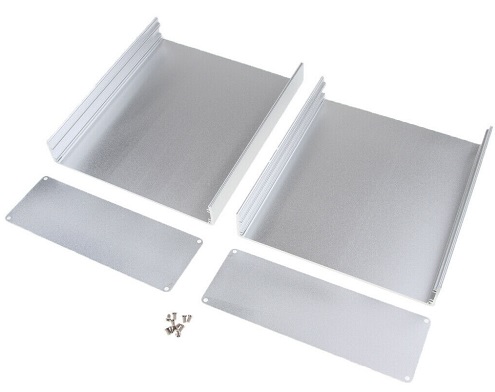
Item nr: 283457585675
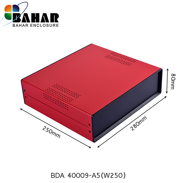
Or in blue, very nice case from BAHAR ENCLOSURE. model nr: BDA40004-A6(W200)
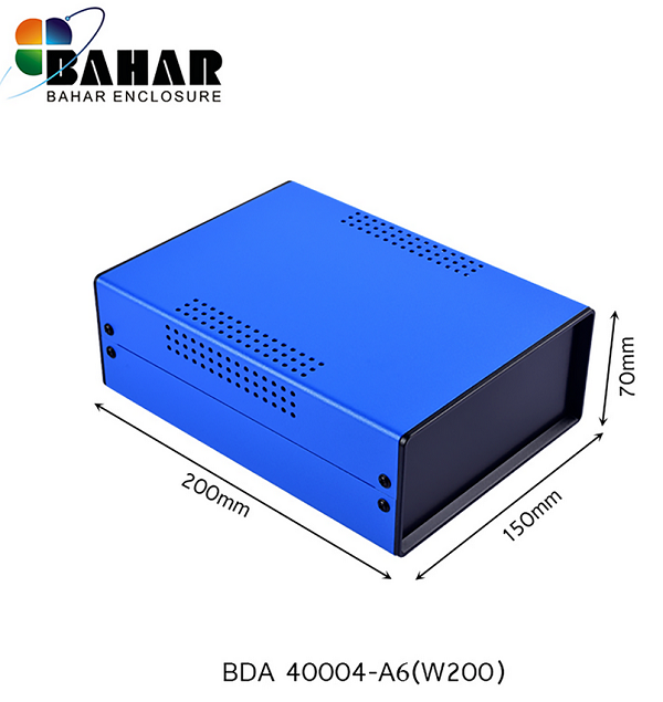
Very nice housing for one unit EE12.
Very nice housing for two units EE12.
For three units EE12, a 19 Inch rack is a good idea. Search for: 19'' Rack 2HE
- Uc is a control voltage for the Socket Board EE12. It is not the actual grid voltage of the tubes. So the control voltage can go into positive range, while the tubes lift their cathode voltage,, due to auto bias, Then, the tube grid-to-cathode voltage stays still negative.
- If control voltage is set too high, at some point the grid current LED will begin to burn, showing you went too far. (The tube grids have become a rectifier diode). Before that happens, the red LEDs burn already very bright, and catch your attention. So without having to know, at what voltage this applies for which tubes, you can already see by the LEDs behavior, when you enter this (unwanted) operating range of positive grid voltage. Also a grid current Panel meter (optional) would show the same, but show this earlier and analog. (With the value in uA). That is because the white grid current LEDs circuits have a (calibrated) limit, below which they do not indicate.