Electron Engine ™
Printed Circuit Boards by Emissionlabs
- Introduction
- Use of Triode Board (EE12) with Power Supply EE11
- Use of Triode Board (EE12) with external Tube Tester L3-3, or other
- Use of Pentode Board (EE14) with Power Supply EE11
- Tube Data Table
 Typical Test sequence (You are here)
- About the purpose of burn in.
- Fusing of the boards.
- Building instructions
- Options and Support
Typical Test Sequence
This arrangement of switches operates from the left to the right.
Note: The heater switch can be a two position switch or a three position switch which is "off" in the center position. Advantage of three position switch is, the heater can be switched off, for whatever siuation that would be needed. Since the red/green LEDs of the heater switch are also "power on" indicator for the whole unit, the red LED still lights, even when the heater switch is in the "heater off" position. We ship with the 3-position switch.
 Step 1. All switches in the lower position, bias turned fully counterclockwise.
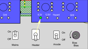 Step 2. Mains on. First comes pre testing. Failed tubes should not be further tested. The green LED indicates 6.3V heating. (We start also 12.6V tubes this way).
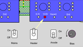 Step 3. Only for 12.6V tubes. They should glow dim at 6.3V. Now switch to 12.6V.
Note: With some tube types there may be a small lighting of the grid fault LED. This is not a fault of the tester, and not a fault of the tubes. This current flows indeed. Without anode voltage, some emitted electrons land on the grid, causing this small current. This will go away, as soon as anode voltage is applied. (In the next step).
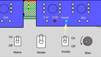 Step 4. Anode On. Hazard LEDs must be on. Since Bias is still zero, there should be no tube current. This is the first pre test. If a tube can not be cut off, as easy as the other ones, this a quality problem of very bad kind. It may improve by burn in, but only when plate current during normal operation is not higher as with good tubes, Otherwise this is a rejected tube, and should not be tested any further. It may seem to work normally in an amplifier, but it may fail early, or develop noise.
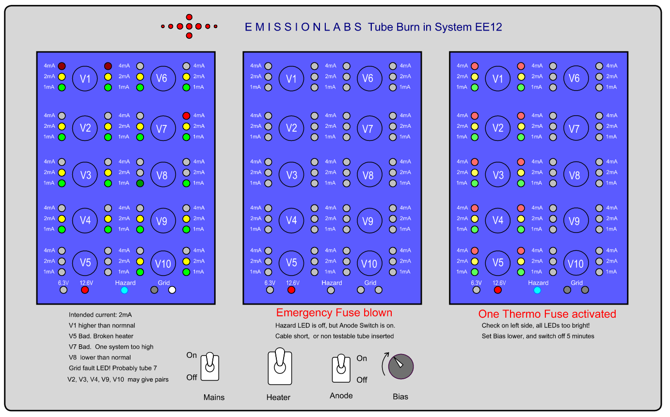
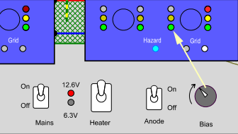 Step 5. Bias Increase. Turn bias knob slowly, and watch for faulty tubes. In this example the tube on the right has one defective section. It draws a lot more plate current than the other tubes. So the left segment is at 1mA (Green) and the right at 4mA (Red). If one section burns at 1mA and the other at 4mA, this is a rejected tube. A difference of one LED can initially be tolerated, but should improve during burn in. If not, such a tube MAY be good, but on a parametric tester it will not appear as a fine quality item, and it will not be possible to match it with other tubes.
Grid Fault. These LEDS may begin to burn quite bright, when the bias is set very high, and the tubes are driven into positive grid voltage. This draws grid current, because the grid acts as a rectifier diode, and the rectified current makes the LED burn. Meaning, it is only a sign, the bias is set too high. Reduce the bias, and the grid fault LED will be off. If the LED will not be off, at low anode current, there is indeed a grid fault with one or more tubes. In that case, remove the tubes one by one, until you find the bad one causing it. If the problem is gone now, this is a very questionable tube.
After this pre-testing is done, and all tubes has passed, increase the bias to the desired level, and all tubes should work normal. At a very small amount of grid current, which you can locate to a specific tubes, you could watch if burn in will repair this. This is not impossible. A similar approach is for differences in plate current. If one sections draws far too much current, it is probably a permanent defect. At smaller differences, observe if this goes away.
Now burn in can begin.
During and after burn in
It is not possible to say here, how long burn in will take. I may range from just hours to one week. In all cases, observe what happens, and stop the burn in when the process develops not as expected. When burn in develops good, all tubes start to become uniform, and not loose plate current. If so, the burn in process is ended.
After this, by changing the bias, it can be seen now, which tubes can be used for matching, and which can not. So this is a real time saver, when testing high quantities. At any difference, these are not necessarily "bad" tubes, but you will not be able to match those well. Depending on the lot quality, 40...95% of the tubes will be able to match.
Very difficult to match are so called computer tubes, since these were not intended for precision. However these were also made for longer stand by time, and it may be possible trying to improve such a lot, by longer pre-heating of the filaments.
Some fault situations:
This picture shows many fault situations. At an overload, the thermo fuses will activate. The emergency fuse will only blow at a full short, like when putting a none testable tube inside, by mistake. Thermo fuses would respond too slow to this.