Electron Engine ™
Printed Circuit Boards by Emissionlabs
- Introduction.
- Use of Triode Board (EE12) with Power Supply EE11
- Use of Triode Board (EE12) with external Tube Tester
- Tube Data Table
- Typical Test sequence
- About the purpose of burn in.
 Fusing of the boards. (You are here)
- Building instructions
- Options and Support
Fusing of the Boards
 When testing unknown tubes, risk on equipent damage is often just very low. This makes the user become uncautious, until the moment comes, the wrong tube was plugged in, or indeed a tube appears shorted. With the EE11-EE12 combination, even then, chances it will only cost you a fuse, are very good.
Please read this part about SAFE grounding
How the Socket Board EE11-EE12 system is fused:
- Over-Current. Each board has two groups of tubes V1...V5, and V6...10, each group with a self resetting thermal fuse of 80mA. Each group can deliver maximum 18Watt anode dissipation into the tubes, so 36 Watt for one board. So even though the whole board is thermal fused at 160mA, also the board will partially switch off when this 160mA is unevenly distributed. Since overload will likely distribute uneven between the groups, with one defective tube, this becomes very effective against errors.
- Mains fuse. The thermal fuses are surprisingly accurate, much better than melt fuses, but the are slow. So for any fast and very strong overload, we still have our mains fuse.
 PCB fuse after the High Voltage capacitor. Such capacitors can release very high energy if shorted, and do damage to the path it takes. To prevent bad damage, there is a PCB fuse after the capacitor. This is just for emergency. It works reliable, but is not intended as a fuse for daily use. When you activate this fuse (for instance a shorted wire on the bench) you have to restore it later, with a thin piece of wire.
 - Temperature. Moreover, since those 80mA fuses work thermally, these supplies also protection against thermal overload in general, no matter where the heat comes from. So in in a closed cage, at general overheating, it may active those (self-resetable) fuses as well.
- Reset. Thermal fuses are slow, but more accurate than a melt fuse, and they are self resetting type. Still it should be avoided to use them as general switch-off devices. If they activate, find out what caused this, and prevent it. If one of the thermo fuses is open, this section (all left tubes, or all right tubes) will show no anode current any more, and the blue Hazard LED is still on. For a reset, the unit must be switched off 5 minutes with all switches and bias setting in the 'start' position. The resetable fuses can be used multiple times, but not unlimited times. So they are not intended only for emergency.
- Prevent testing 6.3V tubes at 12.6V by mistake. At a bad moment, this can happen to all of us. The excessive heater current at start up, may only blow the mains fuse, when all 30 tubes of high current type are inserted. Many times this will not be so, and the transformer just will supply 12.6V to 6.3V tubes, and the tubes will take damage from this quickly. To prevent this, make a good habit of always starting with 6.3V, also with 12.6V types. Then, for 12.6V types, when you can see them beginning to glow even at 6.3V, or glow stays invisible, switch to 12.6V. Like this, over time you will develop a routine to visually check the heater glow. When using this start position as a good habit, you start always at 6.3V, also when the tubes are 12.6V.
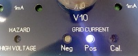
- A grid short. First, a damaged electron tube is not a hard short, like a shorted transistor. A zero ohms short inside a tube, is hard to imagine. The anode current is limited by the emission of the tube, even in case of a failure. A grid short will increase the gird current and anode current a lot, and the red LED will sure catch your attention. Also the white grid fault LED lights up. Depending on the direction of the current, the Postive or Negative LED. If both LEDs light up, there is an AC signal present, wherever it comes from.
- Gassy tubes. A tube can have gas before, or develop gas during testing. Such a tube will show too little plate current, and/or light up the grid fault LED. Ideally during burn in, the tube will self repair, when the gas is absorbed by the getter.
 If the gas is caused by a glass crack, the problem will only become larger during burn in. If a grid fault is indicated, then by removing the tubes one by one, the bad tube can be found. (Switch off before removing a tube). Monitor carefully if a small grid fault will go away, and if not, this tube is a reject. Even when it works perhaps in an amplifier, such a tube will suddenly cause problems later, and should be not further used or tested at all. Do not confuse grid current due to gas, with grid current due to positive grid voltage. (too high bias setting). The last is not a tube defect. It is just when you create postive grid current by over driving, the LEDs indicate this. Since this is not a good test condition, you should reduce the bias accordingly.
 - Zero ohms short. This can only happen when a non-testible tube which was plugged in by mistake. For this, each Socket Board EE12 has a 160...250mA melt fuse, which will activate before the thermo fuses. When the melt fuse is blown, the blue hazard LED will be off. It is possible, depending on what is shorted, the tube grid will deliver or pull current via the gird connection, and in such a case, the grid fault LEDs light up, even though the anode voltage is off. That is because the grid has it's own power supply.
- Mains fuse. If all of the above fails, the power supply board has still a mains fuse. A short of the heater circuit will blow the mains fuse.
- An unintended fusing mechanism. Each tube (section) is grounded finally via the green LED. At a bad short, these 3mm LEDS do not short, but burn out. This is of course not intended as a real fuse mechanism, but it is good to know, this hidden safety exists.
- All in all, I found the Socket Board EE12 hard to damage and easy to repair.