Electron Engine ™
Printed Circuit Boards by Emissionlabs ®
EE21 Board, Moving Coil, Tuning
- Overview
- MC Applications
 MC Tuning (you are here)
- All Connection Schemes, Complete Overview
- Unsorted Application Information
History
Around 1935, the standard input impedance of the record player input of radios was 47k. This specific value was chosen because it would do something similar like an RIAA curve, if a crystal record cartridge was loaded with this value. That was the only reason for this curious impedance, which for the rest if it, is much too high for any other application. So in 1935, radios had 47k for this reason, and we inherited this strange value for audio inputs. Even today, people get a strange feeling in their toes, when the input impedance of an loudspeaker amplifier is not exactly 47k, but 39k. But really, unless it is important for you, to connect a crystal record cartridge, 47k is a silly value, and anyting around 1k would have been a far better value. In professional environments 600 Ohms is used, because it doesn't hum easily.
Yet for RIAA inputs, we talk about something else. As Moving Magnet cartridges found their way into HiFi, logically they were made for this 47k as well, because all radios had 47k anyway. A problem came however with MC cartridges, because these are by nature very low impedance. Like all low impedance devices they work at low voltage, high current. With semiconductors this is already difficult to amplify free of noise, but with tubes it is really very difficult. The MC transformer is our friend here. It can give gain of a factor 32, without adding audible noise. We do not get this amplification for free, because a step up transformer represents a difficult load, and these have to be used the right way. One of the things to look at is the damping.
Damping of the cartridge needle
 Why is needle damping done? It ensures good contact between the groove and the needle. Also called tracking. This is beyond the scope here, but it is obvious that the groove can heavily shake the needle, and the needle may not follow the groove exactly. Needle damping can be conveniently done electrically, by just placing a resistor at the MC Transformer secondary side.
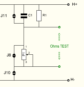
The damping network is universal. For MC applications, C1 is not used. To activate the damping, J10 must be closed, while J8 and J11 are open.
Here is a quick calculator for this. Note, this calculation is for an RIAA amplifier with 47k impedance, and it does not take into acount the DC Resistance of the coils. Though knowing DC Resistance is theoretically needed, we can skip this problem with the EE21 board, because the damping resistor is variable anyway, with a potentiometer.
The RIAA amplifier already provides a 47k damping resistor, which gets connected to H+ and H-. The load of P1 and R1 is additional to this 47k. In some cases, the 47k will be just what we need. In some other cases it will not be so. We can add some more damping. In case we want to remove some damping, this is indirectly possible, by going to the lower gain factor of the board. The lower gain will reduce the influence of the damping by 75%, and we have more range for P1 now. Normally when this is needed, it is also the better choice for the cartridge, so the choice for best sound. This will be explained here:
The relation between needle damping resistor, gain needed, and minimum load specification of the cartridge, is on purpose such that the cartridge works probably good, just by the 47k load, which is supposed to be there already. So when somebody says, he never looked at it, and sound is very good, this is sure possible. But it does not have to be this way.
Why is this so? If a cartridge needs only small gain, the manufacturer knows this of course, but the gain of transformers is just how transformer builders make them. It is a range, and not a fixed number. Knowing this range, they anticipate what this gain does with 47k. (as this 47k gets transferred to the cartridge with the Square Root of the gain). The manufacturer now builds the cartridge such, that it works good with 47k at the RIAA amplifier, and the assumed gain. But there is always this variation of the gain, depending on final transformer choice, and that will give variation of the damping. We can not change the gain precisely (only double it), but we can however change the damping precisely. So for fine tuning, change the damping resistor, is what we do with the EE21 board.
This has quite an influence on the sound character of the cartridge. For this reason, it is recommended to try both gain factors of the transformer, and experiment with the variable damping resistor what results in best sound. Ideally there is an overlap, meaning a damping resistor can be found which works good with both gain factors. If this is not the case, this can also happen. Suppose the cartridge is made for a gain of 15...25x. There is no 'must' that it works at 32x, only to have more volume. Yet it will sound good at a gain of 16x, if the appropriate extra damping can be added. So there will be cases when both gain factors can be used, and with the Option3 (Dual Gain switch) a change between those two sound characters is possible. Also there will be cases when only one gain factor gives the best sound, and the other gain factor is not good to use.
These are just some examples. For board tuning you need to find the values for your own cartridge, using this calculator. ![]() Excel Calculator here. So please note, values of P1 and R1 are depending on the minimum load of the cartridge.
Excel Calculator here. So please note, values of P1 and R1 are depending on the minimum load of the cartridge.
Step up Ratio |
Cartridge (Just examples) |
P1 |
R1 |
|
1:12 |
Benz Micro |
150k |
10k |
|
1:24 |
Benz Micro Reference S Copper |
100k |
4k7 |
|
1:13 |
Benz Micro |
250k |
12k |
|
1:26 |
Benz Micro Reference S Copper |
120 |
6k8 |
|
1:8 |
Clearaudio Signature |
200k |
10k |
|
1:16 |
Denon DL103 |
100k |
5k6 |
|
1:16 |
Denon DL103 |
100k |
5k6 |
|
1:32 |
Benz Micro Reference S Copper |
680k |
33k |
Note: Before board tuning, like above here, first the board needs to be tested for basic function.
I recommend to solder the transformer into the PCB at first with short wire pieces of 2cm, such as the ones cut off from resistors. Like this, it will be easy to remove later.
First, disable the network, by opening Jumper J10. In this condition, the best gain factor of the board has to be found first. The board must not respond with hum, when touching the transformer or ground wires. Experiment with the two gain factors. Basically it must work as expected. If not, find the reason for this first, before final mounting. The solder islands of the boards are very good quality and will not damage easily be a few times soldering.
When it works all good, and the best sounding gain is chosen, the best damping has to be found.
Generally damping does this: If the resistor is too low, the needle can not move fast enough any more, and there is a loss of high frequency. If the resistor is too high, the needles looses groove contact. There will be bad sound, and even the needle jumps into another groove at loud music.
Electrically it works like this: The 47k of the RIAA amplifier is transformed down to the primary side, by the square of the step up Ratio. So with a 1:20 Gain, from 47k is left only 1175 Ohms. This is not taking into account the transformer DC Resistance, but with a good transformer, this will not be a very relevant number. To see how quickly numbers change by squaring them, a step up Ratio of 1:10 would transform 47k into 4700 Ohms. So 4x larger! Here comes a problem: The manufacturers do not like specify the step up Ratio. This means we end up somewhere between 2k2 and 1Meg for the secondary damping resistor, with 47k of the RIAA amplifier being just an average. Because we work here with a variable resistor, we can bypass this whole matter, and simple adjust the damping for best sound. P1 is a variable resistor, so it can just be taken a bit larger we really need.
Addendum
This parts comes really all in the end. It is not required, and it can be done also if the transformer is already soldered in.
Some people do not like a variable resistor P1 in the sound path. However to find out's it's best value conveniently, a variable resistor is the best.
Later, P1 can be replaced by a fixed resistor, which comes at the position of R1. For this P1 is shorted with J8, and can be left on the board. Later is can be used again, by opening J8.
The is the procedure:
- It is assumed the adjustment of P1 is final.
- Close J8, and open J10 (and open J11 when it was closed).
- Remove R1, and measure it's value.
- Measure the value of P1 between the two 'TEST' points.
- Do not measure across the test points, with J10 closed, as this would magnetize the transformer.
- At the empty position of R1, place a new resistor which equals the value of P1 plus the old value of R1. So if R1 was 10k, and the potmeter was 90k, the new value of R1 becomes 100k.
- C1 is not inserted and J11 is open.
- Close Jumper J8. Verify if the 'TEST' points indicate a SHORT now. This is good.
- Verify R1 by holding the ohms meter between H+ and one of the two 'Ohms' Test Points (it doesn't matter which one). The ohms meter must read the new value of R1 now.
- If done, close jumper J10, and R1 becomes active.