Electron Engine ™
Printed Circuit Boards by Emissionlabs
EE20 Multi Purpose Board. Version 2.9
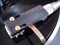
- Moving Coil, Applications.
 Moving Coil, Tuning (You are now here)
 - Audio Board, Applications
- Audio Board, Tuning
- Fault finding
Tuning a Moving Coil System
Generally, a moving coil system is easy to tune. To begin with, it already works without tuning. It is just to do best justice to the cartridge, or allow the fine tuning which you know is possible, and you want to work your way towards to this. In the end, all it needs is a resistor and a capacitor. So nothing very special to do. In order to prevent difficult searching for the right values, we go here a more comfortable way. On the EE20 board is room for a small potentiometer, which is used to find out what value performs best. So just by listening tests, as this can not be measured anyway. It will be explained in the rest of this text how to do this.
Damping of the cartridge needle
 The needle has quite a tendency to make resonance-like movements by itself. These movements will cause an electrical signal, like any movement. The result is: the original signal + something additional. This is nothing else but distortion. If below 5%, it can not be heard as such, but it becomes a specific sound still. Which can actually sound nice if, and it's the magic of analog equipment.
When distortion is too much, you will get tired from listening to it, even when distortion is not audible as such. In some cases then needle skips a groove during a loud music part. Generally, the longer you can listen to a system without getting tired, the better the system is tuned. Often this is not the same as the first impression, or even opposite. Try listening to a soft distorted guitar sound like Santana or Mark Knopfler. It sounds nice, but still 15 minutes is enough of this kind of music for me personally. Whereas with an acoustical guitar, I can hear it much longer before the ear gets tired.
How is the cartridge damping done?
This is done mechanically by the manufacturer already to a large degree. This is a rubber pad, which is pressed between the moving coil itself and the magnet. The rest is done by electrical termination, which is just a resistor, absorbing electrical energy, and it has the same effect, but better under control. Where is this resistor placed?
To begin with, there is already the standard impedance (47k) of the Phono amplifier, loading the secondary side of the transformer with this value. The transformer ratio will transform this resistor to the cartridge, with the square of the transfer ratio. When the transformer is 1:20, 47k will be changed into 118 Ohms. Or, When the transformer is 1:10, 47k will be changed into 470 Ohms. Now, things automatically begin to fall into place here, because such cartridges which are higher impedance, give more signal, but can step up only a factor 10. Whereas low impedance cartridges have low signal, but can step up a factor 20 easily. For such a low impedance cartridge, 118 Ohms is good, and the high impedance cartridge would prefer a higher value, like 470 ohms indeed. So as said, it falls into place by itself, also because cartridge manufacturers know this.
It there is not enough damping, the needle can move too free, and may also loose groove contact, due to resonance, or too loud music pieces. In bad cases it even jumps out of the groove. If there is too much damping, however, this will also make it too difficult for the needle to move fast, and you loose higher frequencies. Often, the 47k is a good compromise to begin with. Read the note from Roger Modjeski. Effectively, individual damping is always worth a try. What the manufacturer describes as "minimum load" is not "the" load, but is a load you should not go below. In the end, it can only be tried out by experimenting
Example for LL9226 and LL9226-XL
Suppose we use an ORTOFON SPU Classic:
- Internal impedance: 2 ohm
- Minimum Load: 10 ohm
- Output: 0.18mv
Please study this as a calculation example, so you can easily repeat this for your own cartridge data.
Let's first see what happens without termination. By using the piano switches, you will soon find out, you need 20x step up, to get the required loudness, without loss of high frequency, and 20x is as high as the LL9226 can go. So the gain is 20x.
Now the minimum load of 10 Ohms transfers into 10(ohms) x 20 x 20 = 4k on the primary side. We take 60% of that, just to hear later what happens at the minimum load, or also below. So this is 2k4, and we take 2k7 because that is the closest value. For the potentiometer, we recommend a value of 150k. (if using a 47k phono amplifier).
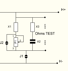
This 2k4 comes now at the position of X1, and with the potentiometer of 150k, we get now a load between 2k4 and 152k. (Leave J2 open). Verify this at the test points, with an Ohms meter. If ok, close Link J1, and now the network is connected in parallel to the secondary side. (H+ and H-).
The potentiometer, you can choose different, we adjust it anyway. After closing J1, this 2k4 or 152k are in parallel to the 47k of the pre amp we already have. So we are now in between 2.4k and 36k, depending on the setting of P1.
The above was calculations. Now comes testing. Try this out. Move the potmeter up and down, and at some point we come much below the minimum load, and latest then it will not sound good any more. Now, just find the best sounding setting of P1.
- In case you want to add a small capacitor (from 10...100pF) as well, you can put a wire link at the place of X3, and the capacitor comes at X2. Probably this won't be really needed, so begin with a small value if you still want it.
- With the capacitor in, try if P1 needs some re adjustment.
- When the setting of P1 is final, you are done.
- On case, when you want to replace the potentiometer by a fixed resistor now, proceed as follows: Open the link J1 and measure the resistance at the test points. Select the closest resistor, and replace X1 by this value. Now close the link J1, and J2.
- WIth the jumper J1, you can now enable or disable the network, to hear what it does.
* In case you intend to use the dual gain switch, find a setting for P1 which works well on both gain settings. This will normally work out fine, because in the end the whole game is always based on the phone amp impedance of 47k.
In short we can say, with too much damping, the sound becomes dull, and at to little damping the needle looses physical contact with the groove. The ideal damping depends also on the weight of the head shell and stiffness of the tone arm. This is why we recommend variable damping, and switch it on and off, to hear for yourself if there is a difference. Do not regard this something "difficult" with Lundahl transformer, or the EE20 board. If you think tuning is not needed, you could also skip it.
Note:
This was pointed out to me by my late friend Roger Modjeski, from RAM Labs, USA; An MC cartridge is a coil, moving in a magnetic field. For that reason it behaves like any electric generator. With all electric generators, the output voltage of the coil, depends on the CHANGE of the magnetic field in that coil. So what causes the field inside the coil to change? With an MC system, the magent is fixed and the coil is moving. If the coil moves very slow, signal will be low, and without move there is no signal at all. With a frequency range of 20Hz, the velocity of the coil changes 40x from maximum to zero. With 20kHz, the same is done 20.000 times in one second, so 1000x faster, as with 20 Hz.
What causes damping? It occurs when the signal generates energy in a load. What causes this energy loss in a resistor is: U²xR. But what exactly, causes the coil to generate this energy? By rules of energy, It is friction x path x time. From the view of the coil, we introduce the Friction with the load resistor.