576 Curve Tracer, General Part
CONTENTS
 General Information about the Tektronix 576 Curve Tracer (You are here)
- Restoration of a Tektronix 576 Curve Tracer
- Measurements with a Tektronix Curve tracer
- A computer Interface for a Tektronix 576 Curve Tracer

Why using a curve tracer?
My HAMEG 203-4 oscilloscope has a simple, but very good working curve tracer build in. This is like those things we think we know it already, because we learned it before. I just took my multi meter, set it on diode test, and that did if for me, most of the time. Actually many people are not aware, most multi meters do this nicely. Just take an LED, test it on diode test, and you'll see it burning at 1mA, and the forward voltage is measured. The multi meter, when it's a good one, will use a build-in current source of 1mA for this. To be sure, just put another meter one in series with the diode you are testing. So the things you'll see are a lot better than testing diodes on resistance test only. Also you will notice, different LED colors have difference forward voltage. All of these things are already known of course, but it's nice to see it working on the bench. Test a 2.7 Zener diode in forward direction, and you'll get 0.7V. Test it in reverse direction, and voila: 2.7Volts. So in a way, and cheap multi meter can already do this a little bit, but forward voltage can only be measured as far as the internal current source can supply, and that is lower than the battery voltage.
This basic, very simply curve tracer of the HAMEG 203-4 oscilloscope is actually a wonderful feature on the bench. Junction transistors, so the normal PNP and NPS, if defective, do not show correct forward and break down voltage any more of the base-emitter diode. (Break down voltage is appr 7V). So a quick look on the curve trace will show if the base-emitter diode is good. If good, the transistor has at least basic functioning.
I found interest in looking at curves of passive components with the HAMEG. I got the taste of this, and I wanted to have a curve tracer which can do also step functions (So step the control inputs of devices).

Basic curve tracer of Hameg HM203-4. It has no settings, just this one it always takes. This is a 10V Zener diode.
If you are interested in basic measurements, I can recommend a Hameg Scope for this. Some people write web pages about how to make a DIY simple curve tracer for 2-terminal devices, or you can also buy some ready made boxes on Ebay for a small price. And then in the end, you need to connect a scope to them. If you consider a scope for Audio, consider the 203-4. It is a very basic, useful model, and the component tester inside comes for free.
The HAMEG sparked my interest for the Tektronix 576. After playing with this option. First I was interested in the Tektronix 570 curve tracer, the first and last one by Tektronix, made for tubes, but all the nuts on Ebay are fighting for the broken ones there. That was no option for me. I decided to go for the Tektronix 576 transistor curve tracer instead, and take the trouble to add the missing heater voltage option, in a fixture.
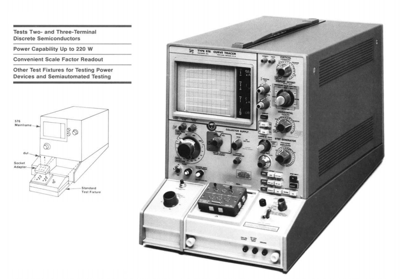
The Tektronix Type 576 Curve Tracer
Then, after I started working with the 576, I began to realize what truly excellent, crazy machine this is. My expectations were so much exceeded. It can do an incredible 1500 Volt and 2 Ampere per division (meaning +/- 12 Ampere full scale), but due to it's very sensitive amplifiers, also go down to 1uA per division. I could have known from the specs of course, but the excellent way this works, just struck me.
Hewlett Packard build their own CRT tubes, and there are some oscilloscope builders who can say that, but not too many. Tektronix is sure one of them. The 576 was first instrument (not an oscilloscope) in series production with a ceramic CRT. So the Ceramics is the outside hull, which is normal made of glass. When looking into old radio tubes, you can see the very nice, industrial types used ceramics parts inside, to replace the mica, So it is a superb material for vacuum technology. WIth the 576, first time the cam switches came into production, replacing the wafer switches. The cam switches have some pro and contra. The disadvantage to me now, as these get older, is deterioration of the plastics. Though I have not seen that yet, it may become an issue in the very far future. Actually the cam switch is not an TEK Invention. Such were used in the 1940's Funke tube testers already. Exactly the same construction, just not for PCB, but with solder lugs. The Funke cam switch is a problematic item, but mainly because fools often tried to bend the fingers, in silly attempts to improve problems caused by axial play. The TEK cam switches seem to have no problems of any kind. Moreover they are for PCB of course, so quite compact, doing complicated switch functions on a small space. What was also new, the 576 was the first instrument to enter production with Tek made ICs. These were used in the readout board, which of course by itself a crazy and unique feature. They created a dot matrix digital read out, by using miniature light bulbs and fiber optics. This unit is amazingly compact and can be pulled out easily. It doesn't work very difficult, and I replaced a light bulb in it. These light bulbs are hard to find, but not impossible. I bought just 10 pcs directly from China, via Ebay. They were exactly the same as the originals. For prices of LEDs. Crazy, but that won't last for ever, I think they will stop making those at some day. So when you have a TEK576 get yourself some of those 5V lamps while you still can. Or, replace them by 3mm LEDs with build in resistor, because the lamps are operated from 5V DC.
Most of all, this read out unit looks is so perfect, it's the best I have ever seen. This was one of the reasons why I have was looking for a 5030 oscilloscope, it also used such units.
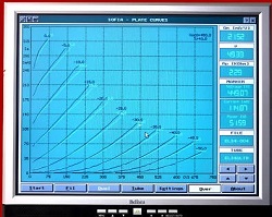 In 1990, the Italian company Audiomatica, build a digital curve tracer (for tubes only) which copied the layout of Tektronix 576. I own two of those. This design is no coincidence. Even using the color of a CRT. The picture you see here, is graphics, on a PC screen. This tube tracer itself is only a metal box. Link to Sofia Tube Tracer.
In many ways, the 576 was a pathfinder for new technologies. I bought mine around 2008. By then they were regarded toys for fools, who can not forget the good old days. Well, I said, so then I am a fool, and I got mine cheap. It was working, though it had it's defects too. Today, as I update this part of the text in 2023, prices are soaring like mad. I think the reason for this is, those cheap digital curve tracers make many people realize how much nice information they can extract from parts, and at the same time realize, these digital impulse testers are not the real thing. If compared to a TEK 576, with it's 12 Ampere, 1500Volt tester, which at the same time can test a small signal diode in very high resolution of mV and uA, these newer devices NEVER will be able to do this. Most of all there are many elementary deficits, in this "pulsed" way to take a curve from an analog device. Such as no RMS power dissipation with pulse testing. Also, with a pulse tester, you can not make negative resistance visible. Such as the firing of voltage reference tube, or even the functioning of a Coherer. I made one myself, and showed it's function on the 576. (Later in this article)
On Ebay I see dead TEK 576 go for 450US$. Well the parts are sure worth it. When the screen lights up, they go for 1000US$, still advertized as defective. Whereas a good working ones go from 2000 to 3500, depending on it's condition.
KELVIN Testing. The 576 can even do that. Same as bench multi meters can test low resistors with four leads. If you have such a bench meter, you probably never tried it. But this method works so nice. You only need four cables instead of two. With Kelvin testing, two leads are used to inject 1mA current into the device. Since this is done with a current source, resistance of those cables, and contact resistance of the meter's banana plugs play no role. At the device itself, the voltage which results from this, is picked up, and again contact resistance and cable resistance plays no role. So simple and so good. Just s set up such test, and you'll be surprized how nice it works, testing for instance the resistance of a relay contact. So measure a 1 Ohms resistor that way, and you'll probably see 1 Ohms. Now do it with the normal two lead way, and you'll see 1.3 Ohms. The additional 0.3 Ohms is the cables. Once you get the idea of Kelvin Testing, you don't want to miss it. But now look... the 576 can do this too.... even when testing transistors. You don't have to, but you can. The original fixtures when this makes sense, they do this by default, and you don't need to "set" something for that. You would not even know, of the fixture uses Kelvin testing. Here, not used to measure low resistance, but to eliminate errors due to voltage drop across the contacts. So you can measure 12Ampere still with the banana plugs of the fixtures. Whereas normally, 12 Amprere needs a fork, screwed connection to avoid voltage drop.
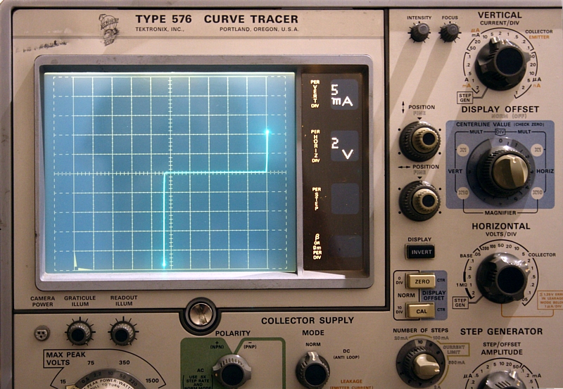
Here is same 10V Zener diode, tested before on the HAMEG scope.
Also I wanted to study a just for my interest, what information can be extracted from components of any kind. Like see the effect of the heater voltage with tubes, and compare two curves charts of a double triode instantaneously. Now of course this can be done with digital curve tracers as well, but that is only half what I intended. A digital curve tracer is very boring to use, because it is not real time, and you have to wait for all the curves to be finished point by point. But moreover a digital curve tracer can not display negative resistance. So you can not take the characteristic of a voltage stabilizer tube for instance.
Displaying negative resistance with an analog curve tracer
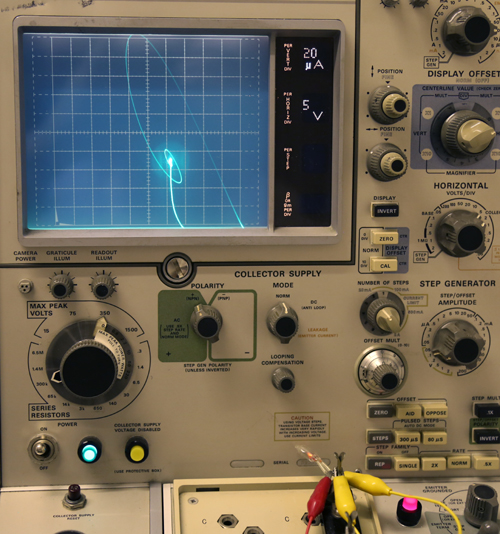
An known advantage of the analog curve tracers is the fact they work analog. So there is the thickness and luminescence of the trace, showing you the speed of the movement. Theoretically this could be simulated by good software, but from most of what I see, designers of digital items have a general problem to study the analog counterparts first. I mean when you are looking at this picture now, this IS in fact digital information, shown on a digital LCD display. So as you can see now, the hardware which you have in front of you, can do it. Just digital scope software can not do it. If you know the reason for this, you know more than I do. Here is another thing which a digital curve trace has problem with, and it's called negative resistance. As a student this was pretty confusing already, and it takes a while before this matter belongs to the tool set inside your head. An item with very typical negative resistance is a neon lamp, which fires. Before firing, and after firing, it is in a positive resistance condition. Meaning, a larger current needs a larger voltage. Just while firing, the current will grow, without increase of voltage, which is something like very low resistance, or even zero resistance when the curve is fully vertical. However current can become so high, ist makes the voltage supply drop, while the current still grows. This is negative resistance. A digital curve tracer cannot handle this, because these work by the fixed principle that one X-value, must give one Y-value. This picture shows what amazing things happen, when a gas tube fires. I used a little neon lamp here, it was the decimal point of a neon lamp digital meter. Click here to see the full picture. You can first see, the sweep is moving to point 'A' so voltage goes only up, and no current flows. Then, when the neon lamp fires, you can see the very strange way it moves to 'B'. This path, this very strange way to get from A to B, you will not find in any book about neon lamps. It describes the build-up of the firing. For the rest, I find this curve very difficult to understand, but for sure is, THIS is what happens with the voltage and the current.
This happens all extremely fast, and you can never show this on a digital tester, which only takes samples slowly.
Digital Curve Tracers
The best digital curve tracer I have, is the Sofia by Audiomatica Italy. The hardware is software protected against overload, and it switches off reliable with tubes. It should be able to test Field Effect Transistors as well, but I am not going to try it. Resistance of FETs is much lower, and I don't know if that was anticipated in the design.
The AT1000 curve tracer has very robust hardware, more forgiving with mistakes, but the software is has many shortcomings, as it cannot work lower than 75 Volts. Resolution below 1mA is in steps of 0,1mA. It is too slow, and curves have no smoothening function. So curves sometimes look like made with a Commodore 64.
There are now some low cost digital tube tracers around, but these are limited in speed, voltage and current. The next lower level would be oscilloscope based testers. Even Tektronix had a module for that for the 7-series scopes, but that is a low power device, hardly suited for tubes.
2. Which one to take, 570 and 576?
There are a few others, but 570 and 576 are the top models. These differ at following points:
570 |
576 |
| This junk they sell on Ebay, looks like dived up from the Titanic, showing how users outbid each other for any price. Sold for 1000 Euro on Ebay Italy, in Jan 2018. It is full of spider droppings, which give those typical white-brown rust pips. Prices up to 4000€ for a good one. | 200...400€ for incomplete, 2000...4000€ for 100% tested. A working one 'as is' for 500..1000 Euro. |
All tube technology |
All semiconductor technology |
Anode max 500V. |
Anode max 1500V. |
Can tests small parts, with low voltage, and sensitive current limiting, 1nA per division. Can tests smallest semiconductors. Or test huge power devices, up to 20A, 1500 Volts, 220 Watts. |
|
No such option. |
Readout card if the option is included. (not always) |
No such option. |
Modular construction. So you can replace, or repair the module |
Can test tubes, and some FETs. Step function only in Volts. |
Can test tubes only with self-made adapter and external heater voltage supply. Step function in Volts or mA. Can test with positive or negative voltage. |
No safety precautions |
Has hazard lamp and safety switch. |
No such option. |
Can be used with some different interface modules. Such as the standard module, a high power module, or a card interface module. |
Quality is good, but not as good as 576. |
Reputation for it's superb quality. |
No such option. |
Pulsed option possible, so you over heat nothing. |
Loud fan, which slows down over time until it gets too slow, and internal parts get too hot. The 570 can keep your coffee pot warm. |
No fan. Machine gets hardly warm. |
Standard round oscilloscope tube, with external graticule. |
Square tube, with internal graticule, parallax free. Graticule has an additional cross hair in bottom left corner, where many curve charts begin. This tube is obviously dedicated to curve tracers. |
No gold plating. |
Some models have almost entirely gold plated components, and PCB's. |
Parts are just normal radio parts, and just normal tubes. This is a great advantage for restoring. When the 570 is older, total restoring may be needed. |
Some parts are just normal semiconductors, and generic part numbers are not secret. Other parts are often special, but almost anything can be found still, with patience, or for a high price. The technical level of some parts is very high, like laser calibrated resistors, but generally these are problem free. |
Reasonable pdf manual available |
First class pdf manual available |
570 is older. |
576 is younger. |
Adapters often incomplete |
Adapters often all missing, and these cost a lot. |
Switch operated. Deck switches are low quality. Any issue can mean trouble. In fact quality is so poor, the Chinese once build a higher quality clone, called GT-2. |
Many deck switches are only to operate relays. The relays do the switching. So any switch problems may be solved just by exchange the relay, which have gold plated socket pins. |
| . | 35kg weight is definitely totally crazy. Postage in a carton box with Styropor chips is a joke. Can only be shipped on a palette. |
Initially I was interested in a Tektronix 570. However, this page is not going to be a tribute to this model. Though they are really nice and very useful, a large objection for me is, the plate voltage can go only up to 500 Volts. Also, the price is totally crazy for what you get. When you use a tube at (say) 380 Volts, the curve chart should be up to 600Volt or more. Otherwise it becomes a bad compromise. Better is the Sofia digital tester, as it can trace up to 750V. Still a tube like 845 cannot be tested under real use conditions at only 750V. You need 1200V for this, or even more.
However, objections with the 570 are many. First, the relation between what you pay and what you get is fully wrong. This is caused by people that pay 4000 Euro for them. Which they may be worth or not, decide that for yourself. In Jan 2018 I saw one go on Ebay (Auction nr 232611931723) for 1032 Euro + expensive shipment. It was said to be stored for 20 years, and that seemed stored indeed, but it must have been in a chicken shack. There was a layer of rust on the whole inside, and from underneath the scope tube socket was white oxide power coming out, and quite a lot actually. Ideally, it was put in the chicken shack in working order by mistake, and you are the person to find it on Ebay. Not so ideally, it was put there 20 years ago, already fully defective by then, and it was considered scrap metal.
Here is the crazy part about Ebay. You can safely buy such a wrecked item. Just check if the scope tube is at least ok, and if the transformers are still good. If not, sell it on Ebay, and the next one will buy it for a higher price when it is cleaned nicely. So when you find out, it is only scrap metal, just cleaning the item a little bit, will already pay for your shipment cost.
With 570, we have the same situation as with all tube testers, people think they can fix any problems with a soldering iron and a multi meter. Then after they bought it, they find out several owners before them already failed. So they're the next one in line, and here comes the problem: Either you buy it from somebody who knows MORE about it than you, and he gave up on it. Well, you will have a hard time outdoing this guy. Or, you buy it from somebody who knows LESS about it than you, and you receive what he left over.
When a 570 was stored dirty, and somebody try to fix the whole thing with contact spray, you will have a hard time cleaning it. Do not confuse this with the later 576! Though so close related part numbers, the 576 is stuffed with the best and finest parts that were available at the time. There is gold plating simply for everything where they had the choice. Even so, most of the switches in the 576 are just, to switch RELAYS. Some of which have gold plated lead wires. That is a total different way of doing things. The many relays were for the card interface which existed, so most functions of the 576 are basically relay operated and not switch operated. Pull out the interface unit, and you will see there is a whole series of connectors behind it. These allow access to all relays, and other functions. Via those, you can for instance disable the vertical sensitivity as chosen by the knobs, and choose another sensitivity via the relays.
Though errors with tube equipment are usually not so tricky, the 570 has just very many of them. The air ventilator has the habit to slow down when it gets older and there is some risk your 570 was over heated at some point in time. So the 570 is something you should not buy unseen. Bringing it back to instrument condition ( in case you dream about that) means a full restoration. So take it completely apart, replacing every bad item you find inside, and that will be many. Just imagine what to do, after you have de soldered a selector switch, and you find it leaky between all contacts. I mean like some Mega ohms between the contacts. Well you could leave it as is, but no... this is nothing for me. Fixing only what seems broken is no option for me. I tried that out with other tube equipment, but when you repair one thing, soon after the next thing gets broken, and this just doesn't stop. Yet a full restoration of a Tektronix 570 will consume half a year of my time, not to speak of the costs, and many of the objections I wrote down here, do not exist with the 576. ( I fully restored mine in just several days work)
So I had to let go of the 570 idea, I just see too much of the usual risk, somebody sell it for reasons he knows damn well, and I don't want to be his fool. Besides the 576 costs only 1/4 of a 570, it can do 3x higher voltage and current. In fact it's quite amazing to see you can have 1uA per division vertical scale, and even zoom in on that a factor 10, with a delay function as with any oscilloscope, thus getting 100nA per division. Whereas you can also set it to 2 Ampere per division, giving 20 Ampere over the full picture tube. Oh man, the range of this curve tracer is incredible.
Generally the picture tube is a bit flickering, but that is something that belongs to the concept, and they used normal oscilloscope tubes in the 570 and 576 as well. A bit of a pity, because special tubes with very long light up time would have been better. Right now, it triggers to the mains frequency, so the horizontal (voltage) is coming from the mains directly, by using a 1600 V AC transformer, and connect that to the mains via a variac. Even so, the relatively low frequency of the mains is more or less the right one, because a higher frequency would give difficulties with the capacitance of devices. (So called looping problems). So the whole concept makes sense, just not so much the scope tube, but that is how it is.
Quality of the picture tube
The graticule of the 576 is inside the tube, at the phosphorous layer, so it is parallax free. The tube is flat, square, large sized, and brilliantly sharp. The tube of the 570 is more old fashioned, round and not flat, and I believe the graticule is not parallax free. For the rest, I trust it is as good as any fine Tektronix tube, though myself I find a green scope tube a bit difficult to look at. One way or another, blue is more pleasant.
 570 tube. Here you see a picture which is not looping the curves very nice. If it was mine. I would not rest until I have found the cause. Or perhaps never find the reason at all, meaning you have to accept this as is. It's just these kind of issues I try to avoid.
So after all those considerations I choose for the 576. At Ebay, every day you can buy a few, but these are always untested of 'expected to be probably good'. Many people have parts for sale. Prices of parts are high, but product offerings are many. The 576 has specific issues too, but as far as I know it is only minor things. So even though complexity of the 570 is lower, you can restore a 576 far more easier to instrument condition, because most things inside are still good. They don't make them like that anymore. Printed circuit boards are glass fiber, gold plated, with thick solder islands that don't come off when you use a desolder iron. Several boards can be removed easily, because you can pull off all wires with small connectors. Exceptions are the readout card, which can be pulled out from the front after you take off the scope cover. (See next pictures below). Also some boards are underneath a layer of other boards, which is not really easy to service, but I went through that, and it was not so terrible to do.