Part 3
Measurements with a Tektronix Curve Tracer
CONTENTS
- General Information about the Tektronix 576 Curve Tracer
- Restoration of a Tektronix 576 Curve Tracer
 Measurements with a Tektronix Curve tracer
(You are here)
Measurements with a Tektronix Curve tracer
(You are here)
- A computer Interface for a Tektronix 576 Curve Tracer
- A Novel Method for testing capacitors
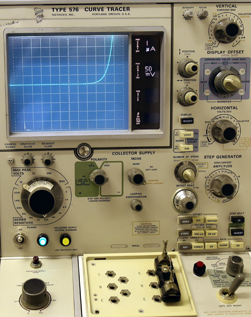
3.1 Testing two-lead devices with the Tektronix 576
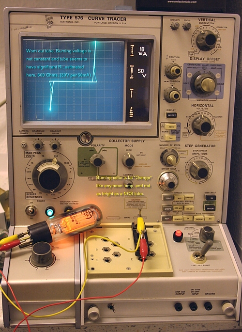
End of Life, GR150DA tube. Apparently working, but testing not nice here.
Here you can see why it may be a good idea to replace the GR150 stabilizer tube of a Funke tube tester. This tube apparently worked normal in a Funke W19 tube tester and it produced the 150 Volt stabilized voltage. This tester tests the tubes with Ug=0V or -2 V, and in this condition specially low Ri tubes react sharply on just a few Volts difference with Anode voltage. So you really want 150Volt and not 148Volt, for the W19 tester to be accurate. GR150 is amazingly accurate, WHEN.... it is a new one. Any used up GR150 apparently work good, but they have much too high internal impedance, and the 150Volts becomes up to 600 Ohms. Which can be in the range of the tubes tested, so that is a bad thing.
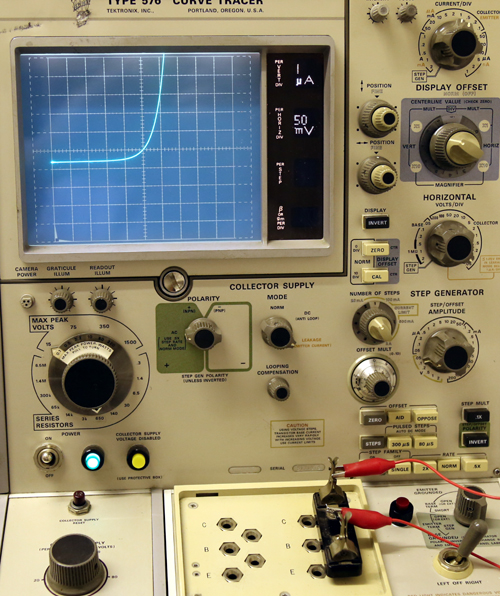
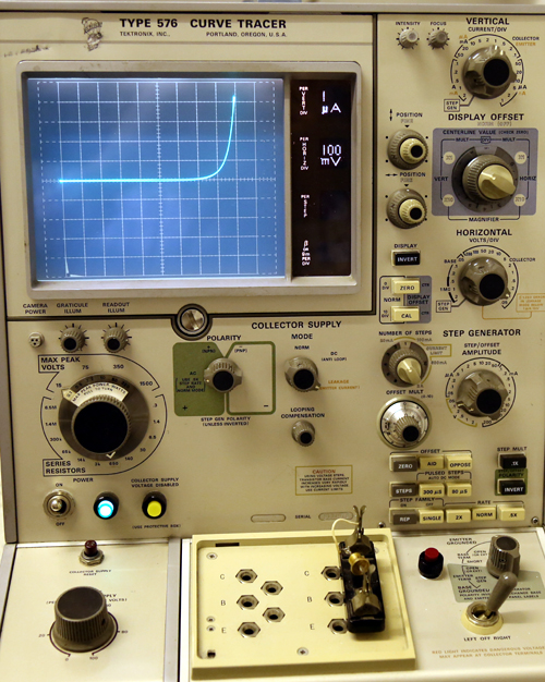
Now, that I have a curve tracer, I can see the difference between a used and a NOS tube, clearly. The NOS behaves like ideal. It has no Ri, and not round cut off like OD3 stabilizers show on this curve tracer. So clearly, this GR150 tube is a very special quality. Behavior is more like a Zener diode, and better than any other stabilizer tube I tested. Though problem with a Zener is very large temperature drift. Whereas this stabilizer has no drift at all. I have learned from analyzing the GR150 with the 576, there is no replacement for the GR150. So replace it by some other stabilizers, and you will never have such a nice, truly vertical load line with Ri=0. Replace it by Zener diodes, and Ri is close to zero, but all Zener diodes have such a terrible temperature drift problem, they cannot seriously be used here as precision voltage reference.
Just remember what difficult and complex things they have been doing in the 1960's with early digital volt meters, to have a precise 10V reference in there. Hewlett Packard put the voltage reference IC in a miniature oven. There are voltage references GR... tubes with the size of a cigarette. I have some here. These give 100Volts, and with a 10:1 divider that gives a near perfect voltage reference. I have one the first HP digital volt meters, and it says in the hand book, they need 30 minutes warm up time to be within specified tolerance. Well these GR.... devices need just 60 seconds warm up time. Much better! Well, but I guess I am too late with this suggestion :)
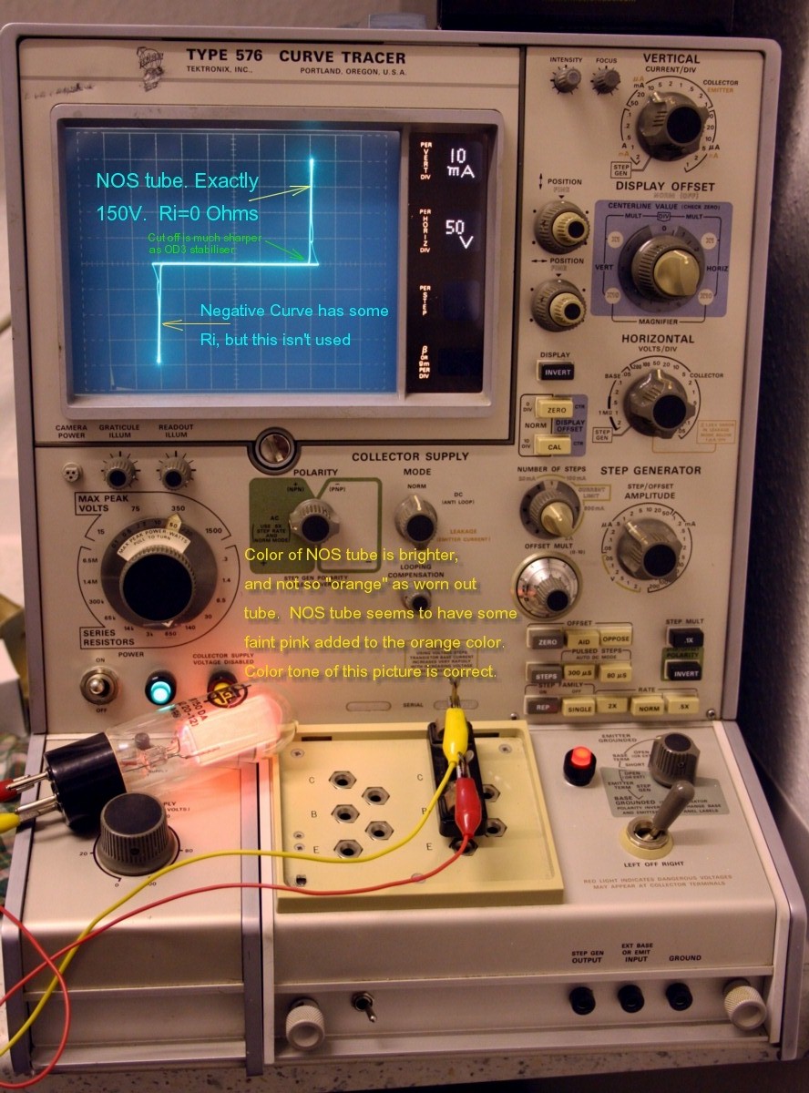
Now, that I have a curve tracer, I can see the difference between a used and a NOS tube, clearly. The NOS behaves like ideal. It has no Ri, and not round cut off like OD3 stabilizers show on this curve tracer. So clearly, the GR150 tube is a very special quality. Behavior is more like a Zener diode, and better than any other stabilizer tube I tested. Though problem with a Zener is very large temperature drift. Whereas this stabilizer has no drift at all. I have learned from analyzing the GR150 with the 576, there definitely no replacement for such a fantastic tube. So replace it by some other stabilizers, and you have not such a nice, truly vertical load line. Replace it by Zener diodes, the load line is better, but these have (TERRIBLE) temperature drift. I suppose GR150 can only be replaced by a very precise electronic made 150V voltage reference.
The coloring of the light of the GR150 tube.
On purpose I have changed the color balance of those two pictures, such that it shows the color of the GR150 correctly. I noticed old, used up GR150 show the normal, dark orange color we know also from Neon lamps. NOS GR150 however, seem to have some other gas mixed with the Neon too. They light up with some 'pink' tone + the normal dark orange neon color mixed. It is such tubes that show this remarkable absolutely ZERO Ohms load line, as I have never seen before with any gas stabilizer whatsoever. At the end of life, this coloring changes to normal dark orange Neon color, and Ri becomes 600 Ohms. So it seems to me, this added fraction of Gas, gets used up until it is gone. Perhaps this is some small form of radio activity which disappears after long enough use, but I have to say I really don't know what causes this.
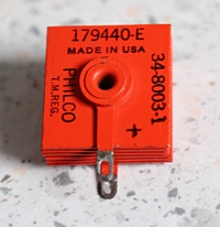
Testing of Philco NOS Selenium Cell Type 179440-E
Curves of a NOS Selenium cell. This is only the forward voltage, the beginning of the curve is at the bottom left corner. Such a nice technology actually from before the day of semiconductor 'chips'. They just created a semiconductor from layers of metal oxide, not even hermetically sealed. Just painted the device and that was it. Provided you can accept some reverse leakage, and for high voltage you had to serialize many, they worked fine. Higher current was no problem. Actually very interesting devices, long before Germanium diodes.
 Break down voltage of a Selenium cell seems an unsharp limit. It just begins to leak somewhere around -70V, which gets more and more. I don't know if that is very good for the cell, so I stopped that, and no pictures.
I expected this Selenium Cell to be able to produce a lot of heat, because of t he it has cooler plates. At some 200mA it begins to warm up a little bit, and it smells faintly like new paint. Same as when you warm up an NOS steel tube for the first time.
Above 400mA the current drops within one second, for some 10%. So it seems that is too much current. When I reduce current back to 200mA, the cell gains the 10% within a few seconds again and stays like that. I was unable to find data about this Selenium cell. My guess is, this is a 250mA cell, and it can produce something like 70...100Volts DC at a forward voltage of 9 Volts. I don't know how much leakage current is allowed. It seems the forward voltage at low current is 4 Volts, and dynamic resistance is 12.5 Ohms. (so 80mA per Volt)
If someone has a datasheet, please let me know, it will retest it versus the original specifications.
I have to say it, I have really respect this old art of making semiconductors from plain metal sheet, just with some coating on it. So put five of those in series, and you have similar performance like a 5U4G. Which is here 20V forward voltage, and you can produce some 400V at 250mA. As a kid, I once took apart a Siemens Selenium bridge rectifier, and I was surprised to find only several layers of dark colored metal sheets in there. I put it back together and much to my surprise it worked normally as before.
Some more tests:
Why Germanium is such a curious semiconductor!
We compare here, 1N4148 small signal Silicon diode, with a similar small Germanium diode, and you will see the amazing properties of Germanium. This semiconductor material has the capability, to rectify any small signal, not matter how small. It needs NO FORWARD voltage at small signal! The only thing you get, when operating below the forward voltage, is higher impedance of the rectifying circuit, which higher impedance, typically at low signal is often something acceptable. So if we need to rectify an AC signal of say 20uV peak to peak, it can be done, but only with a Germanium diode, even below forward voltage.
You can read everywhere, Germanium is no good semiconductor. But is that really so? It depends what you look at. Silicon gives higher voltage, and higher current at the same time, and yes when that is what you need, you won't get happy with Germanium. Though such companies as Harris made some amazing power Germanium power transistors, and also the ASZ16 (tested below here) was a beast, and there is nothing wrong with it. But yes, no doubt, Silicon is better at high power. In reverse, Germanium still is better at lower power. How much better, and why that is, I will show you here, with the TEK576 curves.
Here is a common misunderstanding, we need to get out of the way first. Many people think, small signal diodes are particularly better suited to rectify small signals, than larger diodes. Well, yes and no! Those tiny Silicon diodes cost less, have less leakage, and less capacitance. Which is fine, if is what you need. But how do they get so small? Well simply the chip is cut into smaller pieces, and it becomes a smaller diode. However for low frequency, the smaller chip gives no advantage. It only gives only more voltage drop at the same current! Look at a diode curve, and you will see, the higher the current, the higher the voltage drop. Effectively, the voltage drop is not a function of the chip size, but of the current density. When low voltage drop at the SAME current is important, study some manufacturer curves, or measure some diodes from your collection, and you will see the larger the current specification, the smaller the voltage drop at the SAME current. And yes, the difference is very large.
So the meaning of a small signal diode, unlike many think, is not to work better at low current. This is why in the AVO Mk4 tube tester, you find the (30uA) panel meter protected by very big, 6 Ampere silicon rectifiers. Done so in 1950. Initially, I also thought to improve something, by replacing them with small signal Schottky diodes, but that did not work good at all. I quickly put back in those big, old Lucas UK branded diodes. Reason, why Germanium diodes also did not work well for that function, was quickly found. These diodes have something comparable to leakage current, but it is not leakage at all. Though it works for us like leakage, and they can not used for meter protection.
1N4148 Diode.
The classic amongst the small signal silicon diodes. It can be seen, 1N4148 begins to wake up at 130mV. Below 130mV, there is only very small capacitance, it's like nothing. Above 130mV, it's not a real semiconductor yet, but some voltage dependant, dynamic resistance begins to develop. That's where the diode begins to exist. Below 130mV, it is impossible to rectify a small signal, even when it does not have to be done well. It works not at all. Silicon simply seems to need this minimum voltage before something happens inside the chip, which makes it a diode.
Note also, in the picture above, at negative voltage there is NO CURRENT, and also the curve does not go through the crossing of the X- and Y-Axis. (So the origin of the coordinate System). With the Germanium diode (next picture) this is however the case, which is the magic of Germanium diodes.
Testing an unknown, small signal Germanium diode
 Shown here at the same settings of the previous diode (it was 1N4148). This data sheet is from the 0A70, but the diode under test is another, I do not have the part number of it. By changing the scales of the TEK576 it would look similar. Please read the text of the above Silicon diode first. A Germanium diode, curiously, does not seem to need a minimum voltage before it becomes a diode. It is clearly visible it has some dynamic resistance at ZERO Volt. The angle is appr 45°. So Ri=50mV/1uA = 50kOhms. When going to NEGATIVE voltage, like only -25mV, you will see Ri will be 100k, and when going to +25mV Ri will be only 25k. This has a rectifying effect already. I have never found any good literature on this, but THIS is the reason, why Crystal receivers use germanium diodes, and why they can not work on a silicon diode. It is not because of lower forward voltage.
NOTE THE HORIZONTAL SCALE. IT IS 50mV per Division. I think from -25 to +25mV it is a good diode. And.... there is NO signal distorting due to forward voltage, as there is none, in this mV range. VERY nice.
Make note of this really very strange effect: For rectifying very small signals with a Germanium diode, you can work much under the forward voltage. In fact, totally without forward voltage, and apply 25mV AC on it, as in the above example. If you do, a DC voltage will result! To explain this more simple: Suppose you have a plain network of one Diode and a capacitor, and apply 25mV AC on it. At the positive half cycle (see diode curve) 1uA charge current will flow. At the negative half cycle 0.4uA discharge current will flow. The result is, the capacitor will be positively charged to the point where there is no Ri change anymore. From the curves again, that is somewhere around 35...45mV. So just normal rectification, only at very high impedance. As long as you put only a capacitive load on it, this makes a working rectifier.
So as you can see, you can even use the Germanium diode at a NEGATIVE voltage. So from -5mV to -50mV there is a significant change in dynamic resistance. That will make the discharge of the capacitor greater than the charge, and a negative rectified voltage will result. I remember, being told about exactly this, by my teacher of Theoretical Electronics, and he spend two hours on the subject. I was so puzzled by this, I remember the core of his lessons until today, but I was never able to find much literature about it. The KEY THING to note, a Germanium characteristic goes exactly through the center of the coordinate system. And though forward voltage compares to Schottky, a Schottky does NOT DO so. This makes it impossible to rectify a 10mV signal with a Schottky diode, but with Germanium it's no problem at all. This is so weird about Germanium it is really worth to think about this effect.
- This effect, I have seen only with Germanium diodes. So the 'diode' effect is already there at zero volt, and even below, it stops around -60mV.
- This explains why crystal receivers work so nicely. As the piezo ear plug is a capacitive load only, it even needs a 680k Ohm resistor in parallel as a bleeder for the capacitor. (So it can discharge too). Whereas the diode has 50kOhms as shown here. So it can drive 680k Ohms easily.
- Here is an old Sylvania article, making use of the fact that Germanium diodes rectify ANY signal, no matter how low. What you see here, is a low voltage magnetic amplifier with DC capabilities in the DC mV range. Page1 - Page2 - Whole Book.
Fake Germanium Diodes
Good Germanium diodes are getting expensive in Ebay. One or more Euro each is normal, and the bigger, old ones, go for 10 Euro already. No wonder, the faking industry is working hard on this already. They sell re-painted, re branded Schottky diodes, as Germanium diodes. You'll never get a crystal receiver working on that, but for the rest, if it's only the low forward voltage you need, a Schottky "may" work, but never as good. From what I know, Germanium glass diodes have always a bond wire inside, which you can see, and Schottky glass diodes do not have that, but the chip is solid captured between two pads. Anyway, a Schottky diode, can be unveiled easily as it has no leakage in reverse direction on a resistor tester. Whereas a Germanium diode has also reverse current, which is it's intended function, and the only reason why it can rectify any small signal, for instance like in a radio receiver. Just this appears on a multi meter as "reverse leakage". Whereas a Schottky diode needs a few hundred mV to work at all, and these show also no reverse leakage. This is a MAJOR difference in functioning of a Germanium or Schottky diode. It is what makes a Germanium diode UNREPLACABLE by other kind of diodes in low signal applications.
Testing an unknown, 50 years old Silicon power diode.
This is a gold plated, glass sealed silicon power diode. It was inside a very old amplifier, provisionally soldered in there by somebody. I exchanged it just because I wanted four of the same diodes in there. From there it came into my curiosities box, some 20 years ago. What does the TEK576 tell me? The diode is fine and no break down at 400 Volt. I didn't want to go any further. It doesn't seem to like current above 1 Ampere, that makes the forward voltage go up too much, but it doesn't even get really warm from it. So lets call it a 600mA, 400V diode.
So I know now, this diode is still good, I exchanged it without need.
Testing a Neon Lamp, at ignition point.
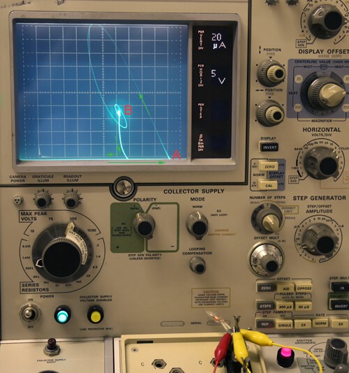
This neon lamp, one was the decimal point of an old nixie display, from a Japanese precision weighing scale. In my previous company, R&D ripped it apart, to see what's inside, and before it went to the bin, I could pick out some things I liked.
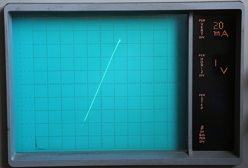
Here is a zoomed part of the ignition. (you can zoom in with the 576). This way of making it visible is only possible with an analog instrument.
I have no good explanation for what I see here. If somebody knows more, please send me an email.
Note, for this picture, the X-Axis was shifted down to the bottom of the display by setting the tester to 'NPN transistor'.
At least the observation is, when the negative resistance develops (at A) the resistance itself is too high to reach point B straight away. Also you can see the speed of the movement, because when it moves fast, the line is thinner. Look at position B, here is where ignition begins, and the line moves up diagonally. You can see, at first it moves slow, the line is thick. At that point, the resistance is -125kOhms, estimated, and with that it cannot reach the bright spot in the middle directly, the angle of -125kOhms is wrong for that. So some kind of longer path is unavoidable.
This is hard to understand. Well at least for me.
Testing of a very high inductance coil.
So you think you have a good inductance tester? These may have problems with very high inductance coils, with relatively high internal resistance. Such coils are made to have a lot of inductance in the first place, and resistance came second. Like that, they can be made small.
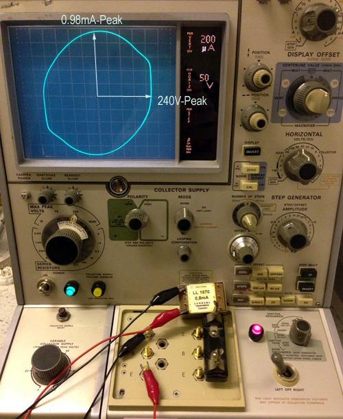
Such a choke is the Lundahl LL1670 grid choke. You can definitely NOT TEST that coil on an induction tester. Well you can, but you get too low result. I had similar complaints from buyers of the LL1670, using expensive electronic testers. Here is why:
The unusual high internal resistance of this part (5k) upsets the impedance bridge I am using. Though this bridge is amazingly accurate, I cannot find a clear balance point at the expected value of 540H. As you can see below there is a balance point at 104H and it's the only one it finds.
So I tested the coil for it's time constant, which is the one and only true way. This is a relatively difficult set up, charging the coil with 0.8mA DC, with a square wave generator at 0.5Hz. This frequency is like DC for he coil, and it charges at the positive cycle which lasts 1 second. Then it discharges via the same square wave generator, when it goes to zero Volt. The discharge current is an E-Curve, and at 62% fall time or rise time, the R/L time of the coil is reached. Due to it's high internal resistance it cannot discharge fast, so the scope is flickering and unpleasant to work with and to look at. A very nasty measurement that was. But it worked and I found 550 Henry indeed, same as printed on the choke, but with quite some tolerance on the measurement, because it reached the limits of my oscilloscope.

Then, I asked Per Lundhal from LUNDAHL Transformers, and he told me, a possible way to measure such coils is by putting a very high AC Voltage on it, with a Variac, until the rated current flows. The current and a voltage will give the impedance.
When this impedance is much above the DC resistance, you can neglect the DC resistance, and Inductance results from * L = Z / (2 * Pi * f * L). This resulted in 700 Henry. Per confirmed to me, the result is correct if measured this way, and internal capacitance gives some deviation. He verified the measurement t for me, using just a normal Volt and Ampere meter, and he found 700 Henry also. The advantage if the TEK 567 is only you need no set up with external instruments or Variac. All of that (the Variac too...) is already build in.
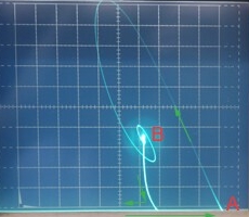
With a 90° phase shift part, you get a Lissajous figure, but as you can see, it is not a nice circle here. I have not deeply looked into the reasons for this. At least it is not saturation, because it looks the same at every voltage, also 10 Volts. Perhaps it is distortion of the mains voltage. That remains invisible with resistors, but becomes painfully visible when there is 90° phase shift between voltage and current.
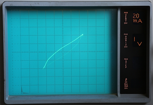
Testing of a very low inductance coil.
This is a coil from a switched power supply, so intended for 50kHz or more. Such a coil will be quickly saturated at 50 Hz.
At small signal, the picture will be a normal oval shape, typical for an inductor. Though I need to go to very low voltage for that, and the coil begins to pick up noise. So such a picture is not a good one. Very confusing, and I will not show it here.
At higher voltage the coil saturates quickly at only 50hz, as can be seen here at appr. 1.8 Volts. So you will see the current go up faster above 1.8Volts. In a way, this indicates the behavior of the B-H curve too. Where the current rises suddenly faster, this is where the flattening of the B-H curve begins. With some math, the curve as shown here could be calculated into the B-H curve.
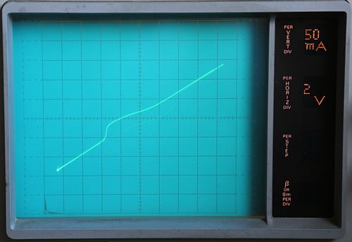
In the second scope picture, the effect becomes clearer. This is the same test, just done at higher voltage, and you can see the coil saturation completely and only a resistor is left. So it ends with a normal straight line.
 Note: The pictures have a thin and a thick line, but that is because of the exposure time of my camera. It would need longer exposure time, but then the picture gets unsharp.
3.2 Testing transistors with the Tektronix 576
This is it's primary function, and it can do so many things, it surprises me every time how nice and accurate it does so. I feel a little bit like somebody using an oscilloscope for the first time. So you make a sweep with from 0V to a maximum positive voltage for NPN transistors (or whatever other device), or switch it for a negative voltage sweep. In accordance with the four mathematical Quadrants , the negative sweep is done from the right to the left, and the (negative if course....) current from top to bottom, but in case that is too confusing for the user, the picture can be rotated 180° optically. Or, you can do an AC sweep, displaying Quadrants 1+3 at the same time. (A quadrant is this here)
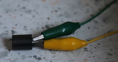
Siemens AC151 Germanium transistor, with collector and emitter reversed.
This is curious, I just tried if this works at all, and it does! Actually it works also with a triode, when you reverse grid an anode. Just such a tube has very low gain, but distortion is a LOT lower than normal, and also anode dissipation gets limited to grid dissipation here.
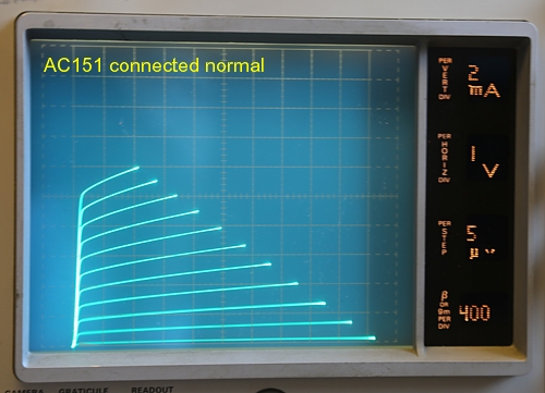
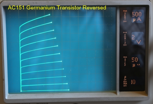
Now with a transistor this works a lot better. It amazed me. Probably such a transistor is not a very good one, but at least curve charts here look nice to me and Beta is not so bad. (One division, so 10x). It is unknown what maximum current and voltage it can do like this, and I didn't want to destroy the transistor to find out. So I stopped at where you can see in the curve chart. Note, what is tested here as collector-base junction, is normally is the base-emitter junction. This means the original base-emitter is now connected in reverse direction, and I don't expect the break down voltage of this diode to be very high, and perhaps break down is destructive too. So I stopped at 10V 5mA, but the transistor responded still very predictable and nicely.
BC558B Silicon transistor, with collector and emitter reversed.
Obviously also silicon transistors can be used reversed, but the curves look not very nice anymore. All silicon transistors have a reverse break down of the base emitter junction at 7 Volt. I don't know why that is, but it's normal and they all have that.
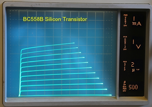
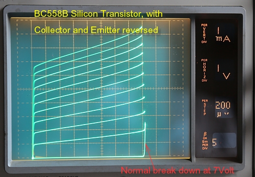
So when we use the whole transistor reversed, what is now the collector-base for the curve tracer, is in reality the emitter-base of the transistor. So these curves will show a collector (base) break down voltage of 7Volts, as you can see from the second picture.
I turned the amplitude knob such that break down just begins with the first curve (200uA), and also the zero current line, show this break down. At higher amplitude there would be a vertical line, beginning at 7 Volts horizontal
ASZ16 Germanium PNP Transistor. 60Volts 8Ampere 30 Watt.
ASZ16 is a beast. It was the work horse from the year 1959, for power supplies and high peak current. I have one here, and it is still good. In those (electron tube) days, with 60 Volts and 8 Ampere, you could do really great things with the ASZ16.
 The curves here, show he curves look reasonable in the low power range. So here at 25 Volts, 300mA. When going to higher voltage, unlinearity becomes absolutely terrible. Fair enough, it's only a transistor for switching or regulating, and such electron tubes exist as well, like 6C33 or PL509. To these have totally bad linearity, but they can do very high current and high power. Same for ASZ16.
This here is just to show at least the transistor is normally working. In the next pictures, I will show some unconventional use, with that same transistor.
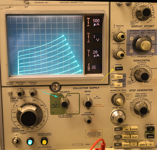
ASZ16 Germanium PNP Transistor, used as NPN transistor
This is quite strange, but with the TEK576 it is just a flip of a switch. (see the green arrow at the left). So why not do it. This inverts all voltages, and it means a PNP transistor gets simply used as NPN transistor. To display the sweep still from the left to the right, the whole picture tube gets electrically rotated 180° with the 'invert' switch. So the green arrow is the electrical invert, and the yellow arrow is the optical invert. The curves look not nice, and they are only nice at very low power, as shown here. The curves seem to sink away under the horizontal axis. (This is not the TEK576, this is by the transistor itself).
With a supply voltages of 20 Volt, the current rises sharply, and it gets all highly unlinear. This is not shown here, but even then, it still works.
A GERMANIUM TRIODE!
For this take a ASZ16 Germanium PNP Transistor, connect it simple reverse, so as NPN Transistor. The base-emitter is now in the reverse direction, it uses no current.
You think this doesn't work? I also thought this.
It is so confusing, trying semiconductors (and tubes) with swapped connections, or reversed voltage. Instead of the device going up in smoke, like I expected with semiconductor, and specially with so called 'primitive' Germanium transistors, it just shows an interesting function. Some of which are strange, and some of which look not bad at all.
Moreover, the devices afterwards always were undamaged.
Well, I have pictured all settings of the TEK576, so it can be replicated when somebody is interested. You know how triode curves of a Germanium transistor look k like? Well here it is, a solid state triode, and surprisingly linear. No, it's more than that. They're the most excellent curves I have ever seen. And hey... this is a 1959 Germanium transistor. I guess nobody ever tried this! So we're 60 years later now.... here you are. A Germanium triode. May be just a little text here and a few pictures, but actually what you see here is very very special, and I have never seen something like this before.
Look at the second picture, this is the same configuration, but now at 20x higher voltage. The curves become so nice, you need to realize these are triode curves, in a more or less ideal shape. So they are almost straight lines, absolutely evenly shaped, and the very low Ra makes the lines almost vertical.
From the second curve chart, I find following TRIODE data:
2) Gain is 1x. So an input step of 2V gives an output step of 2V also
3) Ra = Gain/Gm = 2.8 Ohms
So gain is disappointing, but output impedance is so amazingly low, this can directly drive a speaker. Meaning there is a lot of power amplification still.
3.3 Testing tubes with the Tektronix 576
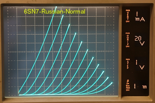
This is a Russian 6SN7. The normal mode is as normal as can be, there is nothing to say about it.
USING 6SN7 at 6Volts, 1mA
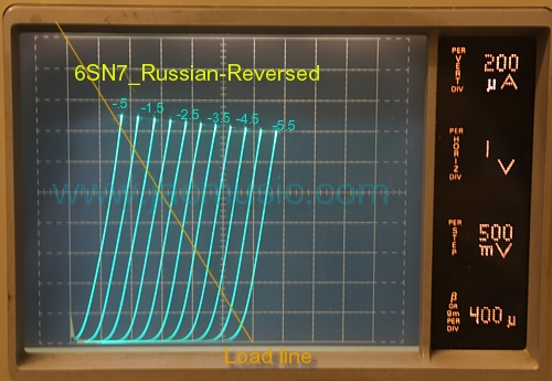
In the second picture, I have reversed Anode and Grid. This sounds unbelievable, but it really works very nice with some tubes, With most tubes there is little or nor useful operation area. With some it works very nice. With 6SN7 seems nice at very low voltage. Interesting is ultra low distortion, a magnitude better than the normal way. Even so, this works here at 6 Volts supply voltage. But it works, and it's an amplifier tube, and I know some people are doing it. (read here)
This is an idea for a battery application, you can use a 6SN7 on a 6V car battery, and get normal (actually quite good!) amplifier function from it.
3.4 Testing other items with the Tektronix 576
A self-made Coherer.
I guess we have all seen a Titanic movie. All these dramatic messages were transmitted by a spark transmitter, and received by a Coherer. The inventor or the coherer did not know how it worked, and discovered it by accident, and it made (digital) radio transmission possible. So not voices, but only 'signal' or 'no signal'.
When you are interested in history of electronics, the coherer is a real specialty. This was the first detector of radio waves, discovered before people had an idea what radio waves really were.
In 1835, the Swedish scientist Peter Samuel Munk, noted how iron filings became conductive after a static discharge in some distance. He did not know what caused it, and nobody had an application or an explanation for it. He was so close to the discovery of radio transmission, and yet so far away. It was not used for 45 years.
In 1890, the French teacher Édouard Branly constructed a sensitive detector of radio waves, and this inspired an Italian inventor, by the name of Marconi, to improve it even further. Marconi was the first to detect radio waves across a few km. His later constructions would overcome 750km at sea. He used the Marconi alphabet for this, his famous pips and stripes. In a later experiment, he used ships to repeat the messages, and Marconi send the first Email from Europe to the USA, via air. Imagine this, he was doing so without understanding how it really worked. Coded not in ASCII, but in Morse, and for the rest there it had all the elements of email already. And no, email is not a mail by computer. Email is an electrically transmitted text message, so I write text here, and the same moment somebody else across the ocean will read it.
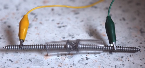
A working coherer is very easy to make yourself. It is nothing but a small container with iron filings, but you need to set it up the right way. It needs a certain shape, adjustment, and the right voltage across it. I used for this a plastic hose, two Zinc plated screws that fit it, and some self-made iron filing. It worked right away, and with lots of trial and error, I got it working detecting the small burst of radio waves coming from a piezo lighter. So this brute device, you see on the left, filled with raw iron filings, is in the range of mega Ohms impedance as long as you measure with a voltage below 4 Volts. So you can't use your standard Ohms meter for that, as these devices use often 9 Volts. The set up needs a variable power supply, a small 6 Volts lamp in series as current limiter, and an ampere meter. Of course the TEK 576 offers all of that, but you can as well set that up another way.
State-1
Non Conductive state
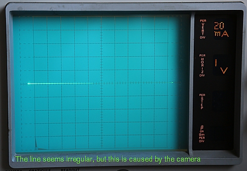
Here comes the amazing thing, which will puzzle you straight away. Build this item as you see here above. Press the iron filings stiff together, and then release it 1mm. It is ready to use now. Test it at 3V and no current will flow. Nothing! You thought perhaps iron is conductive? Well, not like this. You can shake the filings, use a magnet, or do whatever you like. I called this state-1 in the picture.
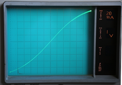
State-2
Unlinear resistance Appr 50 Ohms.
Increase the voltage slowly. Unexpectedly the device becomes suddenly conductive, which an S-Shaped curve. This is an instable condition, but resistance is still positive. There is no way back from here. If you remove the voltage, the effect will stay. If you increase the voltage, impedance will lower further. The device remembers this like a Memristor. I called this state-2 in the pictures. However, this is not yet the coherer effect. You can already now lower the impedance with radio bursts from a piezo lighter. This gets of course nicely visible on the TEK576.
State3.
Conductive State.
There are two ways to get the device in State 3. The first way is just apply a higher voltage for short time. The device with immediately switch to State 3. The second way, is generate a burst of radio waves near by. This will have the same effect.
Note, state 2 will normally not appear after a burst of radio waves. It will rather jump from state-1 in state-3 right away.
Negative resistance. This is what takes the Coherer from state-2 in state-3. So at higher voltage resistance goes down.
Memory effect. Unlike a normal negative resistor (like a neon lamp), there is a permanent memory effect, also when the power is switched off. So, a Resistor that remembers it's current. I don't think I should call it a Memristor, but what is it?
Reset. Once in state-3 you can reset the Coherer by tapping on it. It will jump to state-1
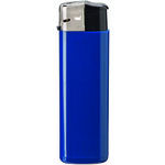
For good functioning you need a few things. So just a little pile of iron filings, and poke two wires in it, will not work. The filings must be in a cylinder, and you need some contact surface. I used big flat screw heads for this. There should be no pressure on the filings, but also it should be not too loose inside. Next is, you need the right bias voltage. It worked best when was close before State-2 begins. So when I see small current begins to flow, I reduce the voltage 0.5V and tap it, to give it a reset. Then is ready to detect. You do need a 'good' lighter, so one that radiates a lot of dirt when you use it. From 7 pieces I found, only one worked very good, and four did not work at all.
All in all this requires a lot of trial and error, but I can tell you it was extremely satisfying when I found the Coherer working. I was able to switch a lamp on, just by firing a piezo lighter in 1cm distance to the coherer.
A Novel Method for testing capacitors
I found this by coincidence on the TEK MUSEUM channel on youtube. I understand of course how the standard Lissajous figure works, as Tektronix advises for capacitor testing, but it seems pretty useless to me. You will see when the capacitor is shorted or open, but that is all.
This text fixture as Bruce Bauer used it, seems much more interesting.
Planned before I die
 Curves of a burning Flame.
There was a patent awarded to Lee de Forest for this in 1905.