What makes a Lundahl mains transformer so unique?
Description
As a distributor of LUNDAHL products, we often get said their Mains transformers are too expensive. Please let me explain here, why they differ so much from regular (low cost) mains transformers. For transformers there are several winding techniques. The lowest cost is the so called M-Core, also called E-I core.
In this article, I will show you some measurements I have made, with Agilent VEE software, but first some general information is explained.
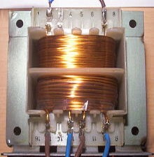 This is a simple E-I Core transformer. Also called M-Core. It has lowest possible cost. The package winding is the simplest. The mains winding is the one part, and the secondary windings are the other part. The I-Laminations are welded to the E-Laminations. The core mains winding is pre-wound and always the same. The secondary windings are custom wound, and the transformer can be put together quickly, at low cost.
Disadvantages are many. Transformer loss and magnetic stray is large, and mechanical hum noise is highest of all types. In such cases where this is unimportant, it must be said this is the product of choice of course, and 90% of all transformers are like this..
There are many ways to make better transformers, but this all comes down to more complex winding packages, und using a more advanced core. The highest technology are transformers with a double windings package (Symmetrical wound). This is the ONLY version Lundahl uses for ALL transformers.
E-I Core with two Chambers (same as above photo)
All problems that exist, you find here.
Layered winding with air Gap.
Most problems are solved with the R-Core, but stray radiation is only partially solved. The magnetic path split in two. Each path is actually not a nice path, magnetic resistance is not the same everywhere. So the "B-H" curve is changing along the path, which gives signal distortion. Distortion results in a range of higher harmonics so 50Hz, 100Hz, 150Hz, etc, for which the human ear is sensitive.
Double windings package transformer
All Lundahls are like this. Also chokes, mains transformers, anything.
Compare with symmetrial wound C-Core with R-Core and it you will see:
Disadvantage of C-Core:
- Twice the windings package needed, a cost factor
- Somebody needs to connect the windings, because every voltage appears twice.
Advantage of C-Core:
- Less iron needed. Less problems from this
- More ideal magnetic path. Similar to ring core.
- Only two air gaps needed.
- Ground capacitance problem solved (See the end of this article)
- ZERO radiation for mains transformers. Each coil half will produce it's own stray radiation. However, due to opposite physical orientation of those fields, the left coil and right coil radiation will have opposite phase and eliminate each other. You will NOT have this with any other construction, only with ring core. However, ring core has many other problems.
- In this topology you find combined the best from all technologies.
Note:
- Just for the drawing, the iron is square here. In reality the iron is oval, and has no corners. (Corners are stray radiation sources)
A HiFi Mains transformer is not just there to get a voltage, but there are also requirements like: low mechanical hum, low magnetic field radiation, low electric hum fields, voltage stability and voltage precision. Here we mention some of the problems that you can have with low cost mains transformers, and how a Lundahl helps keeps those problems on the background.
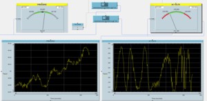
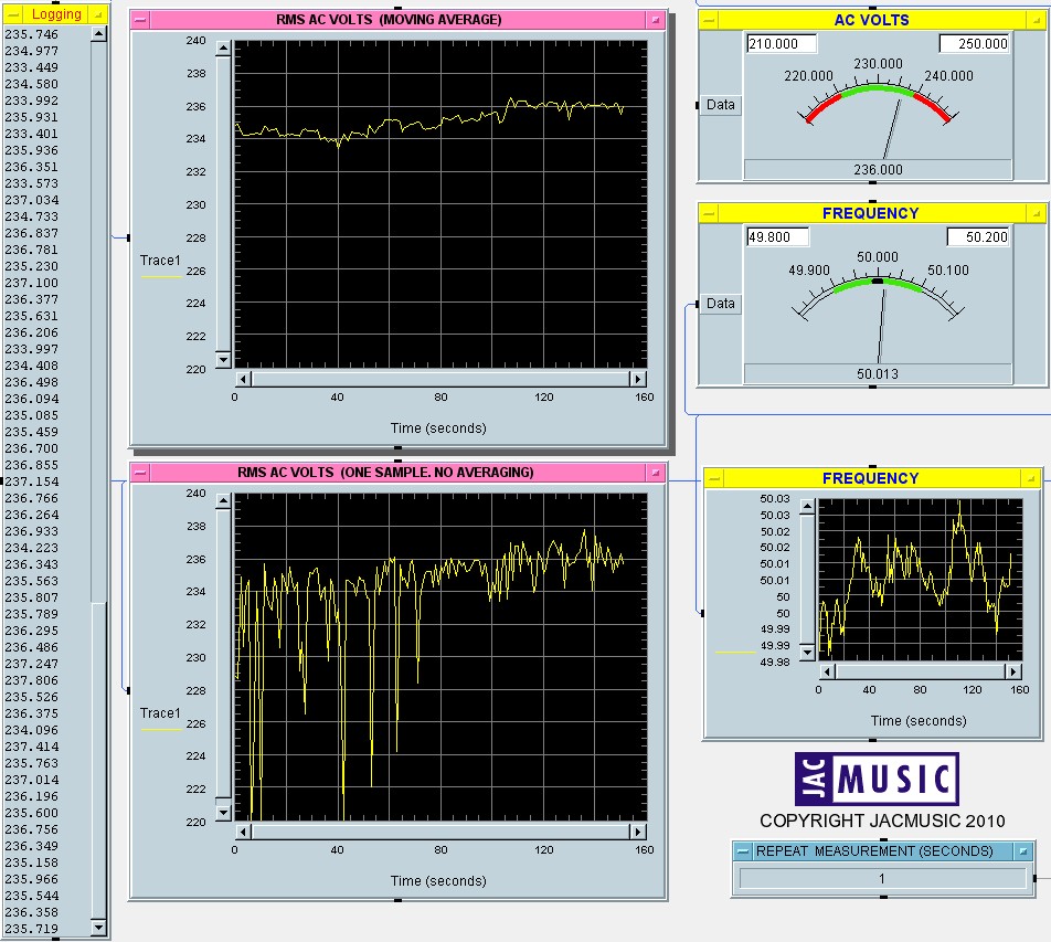
Before explaining why you need a good mains transformer, please look below at those pictures, what the mains voltage looks like. It is not the nice quality that many people assume. Look at the right analog meter called "AC VOLTS". When you have a analog or digital AC Meter, and you measure the mains, it will read 236 Volts this way. The needle is not moving, and a digital meter will change only after the comma, slowly. So you say: "Fine, I have 236 Volts", and you forget about it.
Now, just look what you will see with a top class instrument. Actually with computerized measurements you can make the terrible mess visible on the mains line. I must say when I ran the test, I was ready for something, but the results were really much worse than I expected. So I thought it was a good idea to present this here.
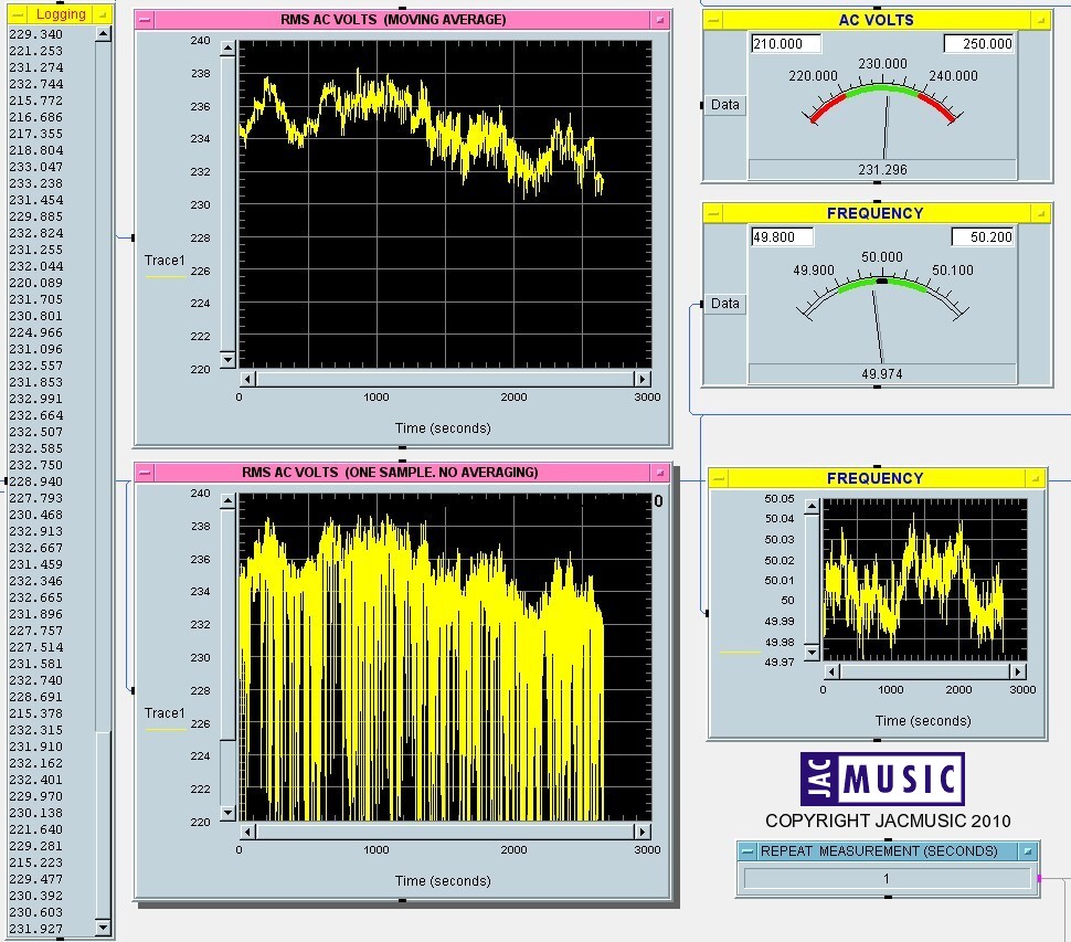 CLICK HERE FOR THE SAME PLOT, BUT NOW FOR 3000 SECONDS
Result of measurements with Agilent VEE program and Agilent 34401a Multi meter
What you see here is following:
- Logging: Last 40 measurements (one per second)
- RMS AC Voltage. Moving average.
- RMS AC Voltage. ONE SAMPLE. This means the RMS voltage is a single sample. So still RMS, but the fastest the meter can do. When the mains is instable, like 228,232,228,232, this is what you see.
- Frequency. Frequency has no impact on the choice of the a Lundahl mains transformer. (I found the mains transformer of Hickok tube testers are NOT well suited for 50 Hz, but that is beyond the scope if this article)
This plot was made over 160 seconds with the Agilent 34401a Multi meter, one of the finest for R&D purposes, with 22 bit accuracy. Measurements can be made single, or with delay. In the delay mode, the meter is averaging a number of repeated readings. In fact it can do both at the same time, and measure the frequency simultaneously. So the physical instrument has one display, but via the data cable, you can tap multiple displays, which show up in the software. I have used a program called Agilent VEE. So this expands the possibilities of this Multi meter very much. In VEE you can write the results to your hard disk, or Excel, or to a digital computer scope which is part of VEE.
This plot was made just in my office here in Germany. Now, what can we see from these measurements? Well .... you can see you need a good mains transformer.
Let me explain the measurements.
LOGGING. These are the numbers as they are streaming out of the Multi meter, in the sample mode. The numbers in the averaging mode, and frequency are not shown here, but these tables also exists.
RMS AC VOLTAGE. MOVING AVERAGE. Here, the meter's internal averaging. method is used. So when the voltage is instable, like 228,232,228,232, the result would be 230. Same as when looking at the front of the meter, set it for RMS, and read the display. The average value (like a normal meter shows on the display) is much cleaner. When you connect any normal voltmeter to the mains, you will see a steady voltage since it averages out the values. However, I have displayed both plots here, to see. It is very hard to give good interpretation to this, and what it can do to your equipment or not. However, I can only make the conclusion a mains transformer nowadays has to deal with larger problems than 25 years ago, when the world was analog. People were yet not loading the mains aggressively with phase cutting electronics, AND not pumping back in energy from solar panels, which uses phase cutting electronics as well.
RMS AC Voltage. ONE SAMPLE. You will see the mains voltage go up and down from 220 to 236 Volts in fractions of a second. So that us too fast to say the "MAINS VOLTAGE" is changing (so fast). It means rather there is so much dirt on the line, the Voltmeter at THAT MOMENT indeed sees the higher or lower voltage. Mind you these are still true RMS measurements, they take minimum one full period, these are not peak or momentary measurements.
FREQUENCY: The plot is interesting, because it shows the total load of the electricity generator (large machine) where ever it is located. When the frequency is suddenly above 50Hz, it is idling for a minor fraction of a second. If it jumps down quickly below, there is a high load switched on suddenly. Actually your house is serviced by more than one generator, at different locations.
So how is how any transformer is going to react on this, and most specially the low cost ones:
Problem sources can be:
- Mechanical hum
- AC Electrical Field
- AC Magnetic field
- AC current signal flow through the ground capacitance
All four together can be very disturbing, not only with tube amplifiers!
For instance with a KT88 design, voltage stability and precision means a 6,6 Volts KT88 filament winding should not rise to 7,2 Volts when a 250 Watt transformer chassis is "only" loaded with 100 Watt. In case you find the voltage of one winding depends too much on the total transformer load, you have a quality problem here. Not only is the unstable voltage by itself a problem, but most likely this transformer is constructed by a low cost concept. It means magnetic paths inside the core have too much magnetic resistance. The result of this is what you measure with your voltmeter. What is harder to measure is the stray radiation caused by this. What you expect is one thing, but what you get after buying the transformer is reality. And as we all know, once you have too high filament voltage you expect the tube tolerance to digest it. Poor tubes.
We found the Lundahl's to be very honest and precise in their specifications. The correct voltages applied to the tubes will increase the lifetime of all tubes a lot. Mostly this is an issue with DHT tubes, but in the end it will become an issue with any tube.
![]()
Ground Capacitance problem, and solution by Lundahl.
With normal transformers (Top picture) there is always a certain capacitance between the mains winding and the chassis core. This capacitance is larger then you think, because it adds up from each single winding! Over this capacitance is the mains voltage applied. With some simple math it can be calculated what AC Current will result when 220Volt AC is applied over a capacitor. What is hard to say, will it cause hum, or not. Before you say no, you should know why you say this. It is actually hard to to say, and the risk is larger than -*9you think.
With Lundahl transformers they use the so called method of electrical compensation. It means they transformer is split in two symmetrical, identical sections. Each will have it's own AC ground current, in this drawing called I,1 and I,2. Because of the special windings technique, these parasitic currents flow in the opposite direction, and effectively cancel compensate each other that way. This takes some time to understand how it is done, but it explains why the whole transformer package is present two times! So if you have your transformer primary and secondary voltages, there are TWO transformers like that on the C-Core. These TWO are paralleled or serialized in the right way to give the required voltages, at ZERO radiation. .
What you see on the bottom drawing is only the primary winding. Each half winding is on one side of the C-Core. Since the primary winding is physically split in two, all secondary windings must be present two times also. This must be done for reasons of perfect symmetry, otherwise the target of zero radiation is not reached.
THE PROBLEMS:
- Mechanical hum can reach the preamplifier tubes when the transformer is mounted on the chassis. This cannot always be "heard" by the ear, but still is conducted to the pre-amp tube. So you start to increase power supply capacitors, etc., but never solve this problem that way.
- Electrical field will stray into any high impedance part of the amplifier. Electrical fields radiated by bad transformers can be very high gradient fields. Luckily the "impedance" of those electric fields is high. Impedance is not the right word for it, buy by this we means an electric field can only generate a signal on loose wires when those wires are connected to some circuit of high impedance.. like in tube amplifiers.
- Magnetic field radiation is harder to deal with. These represent much more energy, and they will find their way into low impedance circuits too. They do tend to generate lower signals in loose wires (exposed to the field) but these signals are very lower impedance, and they will make currant flow in almost any circuit. Besides they are hard to shield. Magnetic fields can pass shielding easily. .Any wire will pick up an AC signal when it is held into a AC magnetic field. Already a straight wire can do this. There is no good way to prevent signal pick up. Take a magnet at home, and try it what it takes to shield the magnetic field. You will see it passed through metal easily. So the best is not to have LOWEST magnetic field radiation (stray radiation) coming from your transformer. The one and only way for this is to have the windings tight together. Hand wound mains transformers do not fulfill this requirement. Next is, you need to have a possible flat copper package. So the outer windings are still close to the iron. Check a Lundahl, and you will see no transformer has such short distance of the outer windings to the magnetic core. Also each wire is nicely in parallel to any other. These are HiFi requirements for mains transformers.
- Ground Capacitance. This is explained in the above picture. With all mains transformers there is a significant capacitance from the primary winding to the core, and by this to the chassis ground, and to the secondary windings as well. The problem is often that the AC current resulting from this is hard to measure, and it is hard to say how it will flow. It will follow the path of lowest resistance, but we can't say what that is in a given circuit diagram.
You avoid hum the best way by not introducing the above problems! Cure it at the beginning of the HiFi chain, and the mains transformer, so you don't need to cure it afterwards. May be you have been in the situation before, where 10.000's of microfarad power supply capacitors did not cure the hum. Also you may have seen (and heard) that good amplifiers can be fully hum-free without oversized capacitors
THE SOLUTION:
With classical transformers (Not Lundahl) you have a primary winding package, and a secondary winding package. Lundahl has a brilliant way to make their mains transformers. This results in a fully symmetrical construction. They use no separated primary winding and a separated secondary winding. On the LUNDAHL mains transformers, the whole configuration is present two times. So on a 250 Watt core, are actually wound TWO identical transformers of 125 Watt. Each copper package has it's own primary. The windings of those are serialized or paralleled in order to get the required voltages, and by this it is possible to eliminate most of the parasitic current, flowing through the ground capacitance. So ground capacitance cannot be avoided, but the current trough it can be greatly reduced. This is a mains transformer to be proud of.
CONCLUSION:
I have studied power electronics and electric energy distribution, so I hope I did not explain it too difficult. I can only advise you to take the best mains transformer, since all in the end vague and impossible to localize hum problems are occurring with low cost products.
Just for your information, Lundahl mains transformers are made with old fashionend paper isolation for lowest mechanical hum. Though newer plastics were used for some time, it appears plastics have more aging over a longer period. So Lundahl went back to good old paper isolation again.