About the kits here
Last Update:
We often gets questions like how to build a GM70 or 2A3 amplifier, or what is the 'best sounding tube'. Well, most of the sonic results depends using the right tubes, use them as intended, not save on transformer quality, and using circuits which are well engineered.
The thing is, most users do not know where to start. So they search the internet for information, and usually end up in some forums, getting stuck in confusing discussions by people who pretend to know a lot about specific tubes and concepts, and in real life never build or tested it.
What you want to know is probably this:
- What is a good circuit. (Good sounding, problem-free circuit)
- What components are used, and where can I get them
- Who will help you when there is a technical problem. (free phone support, Email, etc)
I started this page just new, and the intention is to offer some circuits here that are tested, and guaranteed to work and build without problems, and some others which I think will work, but may need some tuning here and there. These are the ones called "preliminary".
If you are interested in building those kits we have two 'goodies' to offer:
- You get 10% discount on the total order. Just be aware we have no 'ready packed' box as a kit, but you need to select all components yourself, based on the schematics. So you can choose low cost Chinese tube sockets, or the better Yamamoto. Choose silver-oil capacitors, or the lower cost types. Etc. When we prepare the quote, please ask this 10% discount, and mention which of the schematics you are building.
- When you have a picture of the ready build amplifier, and we choose to place it here, we reward you with a 100 Euro free order from the jacmusic website
Sakuma Ground System
 The late Mr. Sakuma owned the small Concorde restaurant in Japan, where he was serving personally, only one menu: A Japanese style Hamburger. The picture here, is from his restaurant, as it was closed down later. During visits he played for the guests music of their choice, on one of his many self build tube amplifiers, which were on display in the restaurant. He used a very clever system to reduce tube distortion, without feedback. I honor him for this, and call it the Sakuma Style. I tried this out myself, and it is impressive to see how well this works. This GM-70 amplifier kit, further down on this page uses this method. With tube amplifiers, we all know, hum prevention is important. Mr. Sakuma simply connected the ground from the input to the output, with a thick copper wire. (Consider silver wire for this, we have such wires on stock). This wire, he used as ground. By this he does not have to worry, were the "ground reference" is. I noticed, also the Italian tube specialist Andre Ciuffoli, credits Mr. Sakuma for this grounding method. Please look at this schematic of a RIAA amplifier for instance, and you will see the ground line, going all from the left to the right, ending at the output. The parts which are gounded, must be connected in the same order, as in the circuit diagram. The late Mr. Sakuma owned the small Concorde restaurant in Japan, where he was serving personally, only one menu: A Japanese style Hamburger. The picture here, is from his restaurant, as it was closed down later. During visits he played for the guests music of their choice, on one of his many self build tube amplifiers, which were on display in the restaurant. He used a very clever system to reduce tube distortion, without feedback. I honor him for this, and call it the Sakuma Style. I tried this out myself, and it is impressive to see how well this works. This GM-70 amplifier kit, further down on this page uses this method. With tube amplifiers, we all know, hum prevention is important. Mr. Sakuma simply connected the ground from the input to the output, with a thick copper wire. (Consider silver wire for this, we have such wires on stock). This wire, he used as ground. By this he does not have to worry, were the "ground reference" is. I noticed, also the Italian tube specialist Andre Ciuffoli, credits Mr. Sakuma for this grounding method. Please look at this schematic of a RIAA amplifier for instance, and you will see the ground line, going all from the left to the right, ending at the output. The parts which are gounded, must be connected in the same order, as in the circuit diagram.
|
20B- Preamplifier and Head Phone amplifier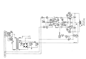
This is not so much a kit, but just a series of recommendations for head phone or pre amplifier amplifiers, using the 20B-V4 tube. Some people and companies have build their products like this or similar.
Read more.... |
Mains Balancer + Adaptation from 230-240-250 to 230V.

This here is not a kit, just a good schematic, and all we have for sale for you, is the special Lundahl transformer, at the regular price. All other parts are standard off the shelf material which you may already have even.
This example is not about HiFi equipment, but about my 1954 Hammond B3 organ, which own since 1990. However, it was my ultimate experience with unbalanced power lines, and it took me 20 years to solve this problem!
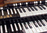 As it appeared later, the problem was the electric field, and not the magnetic field. The B3 is build entirely with tubes, and has a mechanical tone wheel generator, which supplies As it appeared later, the problem was the electric field, and not the magnetic field. The B3 is build entirely with tubes, and has a mechanical tone wheel generator, which supplies
More about it
|
300B Classic Amplifier, DC coupled.
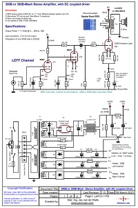 This is a DC coupled Stereo 300B amplifier, without savings on a good power supply. All transformers are the high quality Lundahl. This is a DC coupled Stereo 300B amplifier, without savings on a good power supply. All transformers are the high quality Lundahl.

Specifications:
- Input Sensitivity: 0.7V
- Output Power 7.1 Watt per Channel
- Output impedance 8 Ohms
Read more about it here |
300B-mesh, NF2 Amplifier. NF2 circuit by K. Anzai, JAPAN.
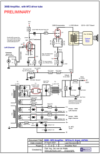 This circuit was added here on request by a customer who wanted to use the NF2 circuit, but preferred 300B-mesh as output tube. This requires a higher voltage power supply, as when using AD1, so also the power supply was changed. The working point is optimized for Emission Labs 300B-Mesh. This circuit was added here on request by a customer who wanted to use the NF2 circuit, but preferred 300B-mesh as output tube. This requires a higher voltage power supply, as when using AD1, so also the power supply was changed. The working point is optimized for Emission Labs 300B-Mesh.
Specifications:
- Input Sensitivity:
- Output Power 7.1 Watt per Channel
- Output impedance 4 / 8 / 16 Ohms
Read more about it here |
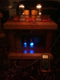
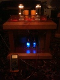
GM70 Dual monoblock amplifier.
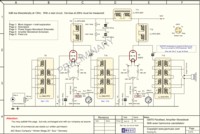 Parafeed and Sakuma principle. Parafeed and Sakuma principle.
The Japanese Designer SAKUMA, is famous for driving an 845 with an 845, to fully cancel harmonics. We do so here, driving a GM70 with a GM70.
Read more about it here
 |
 |
| Left monoblock |
Right monoblock (Just mirrored,
but it looks the same) |
The picture you see here, is by Philippe M. from Switzerland.
|
Schematics by Dipl. Ing. Leven
- 300B-XLS PSE or SE
- KT120
- EML1605
 These designs aim for practically lowest noise, and lowest distortion, yet not overstressing the tubes. Schematics are on 4tubes.com -> Go to "tube schematics with LUNDAHL Transformers" and then choose: LEVEN. These designs aim for practically lowest noise, and lowest distortion, yet not overstressing the tubes. Schematics are on 4tubes.com -> Go to "tube schematics with LUNDAHL Transformers" and then choose: LEVEN.
Read more about it. |
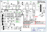
AD1, NF2 Amplifier. K. Anzai, JAPAN. Also used by Jean Hiraga.
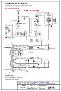 I was not able to find much about Mr. K. Anzai, Japan, other than that he was a circuit designer from Japan. If someone can find some more, please let me know, so I can place it here. Some people report this schematic was also rebuild by Jean Hiraga. I was not able to find much about Mr. K. Anzai, Japan, other than that he was a circuit designer from Japan. If someone can find some more, please let me know, so I can place it here. Some people report this schematic was also rebuild by Jean Hiraga.
Also the schematic shows great resemblance with the Yamamoto AD1 amplifier, first generation. The resemblance is very large, probably there are some connections.
Read more about it. |
| |