Tube Amplifier Kits
P R E L I M I N A R Y
300B-mesh, NF2 Amplifier. NF2 circuit by K. Anzai, JAPAN.
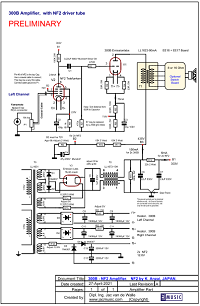 This circuit was added here on request by a customer who wanted to use the NF2 circuit, but preferred 300B-mesh as output tube. This requires a higher voltage power supply, as when using AD1, so also the power supply was changed. The working point is optimized for Emission Labs 300B-Mesh.
When ordering materials, you get 10% discount. This can be when you order it all together, or when you order some parts later too. Like upgrade to Yamamoto sockets, etc. This is not done automatically, so please ask for it when ordering and it will be processed with 10% discount.
Resistors we don't sell. Capacitors only when there is an order number for it, in the parts list (all below here). Though not on the parts list, consider the transformer caps from Lundahl, these are from magnetic shielding steel, and the top cap can be opened while mounted, and you can work or measure on the wiring. They're really convenient, and very good looking transformer caps, powder painted so they won't scratch, and with decent Lundahl logo on it.
A potentiometer is used at the input of this amplifier. Of course you can removed if when you don't want to use it. In that case it is recommended to add a grid-to-ground resistor to the NF2, of 4k7.
SE Transformers used are from the Swedish company Lundahl, which are amongst the top-five best transformers on the world. They are comparable to ring core transformers, they look indeed a bit like a 'ring' if you look closely, 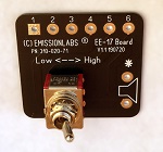 However, the disadvantages of ring coil winding are not present here since the windings package is flat. This is a very interesting construction with only advantages. We have choosen here for the Lundahl LL1623-90mA transformer, in combination with the EE16-EE17 impedance adapter board. This allows a quick change from 4 to 8 Ohms, by means of an external switch, or internal wiring, as you choose. We have also a board to switch from 8 to 16 Ohms the same way, with LL1623-90mA transformer. More about this here.
Low Hum is achieved by DC heating of the NF2 and the 300B-Mesh. Also good and correct wiring is needed to get the hum at or below 1mV, but this is possible with reasonable effort. See the additional notes at the power supply for this.
The mains power supply uses also a Lundahl transformer, which is in it's base construction the same as a tone transformer, so it is not a low budget mains transformer. Advantages are extremely low hum, virtually no stray radiation, and very low heat loss in the transformer. For the rest we have to say this power supply has a special capability to reject a small DC component as sometimes present on the mains. Low cost mains transformers can be found for half the price of a Lundahl, but that would be saving money at the wrong end.
As Power Supply choke, we use the Lundahl Dual Coil chokes here at the finest of their possibilities. it is called the Common Rejection Mode, so the choke is used as a 1:1 coupling element, short circuiting common mode signals, and bypassing differential mode signals. So it is signal filter and power supply choke at the same time. A miracle, nobody ever patented this. This is a choke with two 5Henry coils on one core. The outgoing DC current is passing through one coil of the choke, and the returning current through the other coil. The DC signal is serialized, but the AC stray field (called 'loss induction') is in anti phase for each coil which results in lowest hum possible. For calculations, this makes the choke act as 10Henry choke.
For the tube rectifier an electrical symmetry point is created with two silicon diodes. I quote Per Lundahl's words here, that such a center tap will prevent mechanical hum, since it will per definition divide the transformer flux over two windings, at the moment the mains makes one half cycle. So it means if there is the positive cycle, the current flows still through both transformer halves still. Same for the negative cycle, but in the other direction of course. Still each cycle passes the rectifier tube the normal way. This will give a dead-silent operation of the main transformer. Try out the current path, and you will see!
The rectifier tube used here is 5U4G mesh by Emission Labs, or with another socket you can use 5Z3 mesh from Emission Labs. It is very interesting to replace rectifiers by different types! Theoretically this makes no difference, but from blind hearing tests I once did with the Luxembourg Audio Note distributer, I changed my opinion. We did hearing test on the Audio Note, Mei Shu, 300B Amplifier, and we changed the rectifier 5U4G to 5U4GB. The difference was audible, neither tube sounded better than the other, but they did sound different. It was sure to use good, new rectifiers, that I brought myself and tested before. So since then, I speak against my engineering knowledge, and I say yes, rectifiers do have influence on the sound. So I always encourage people to try some different kind and difference brands. In this amplifier published here, you can use 5U4G and 5Z3.
Sound from 300B and NF2: Please do not ask by an email description about sound, but a little bit we can say. 300B-Mesh has a special sound of it's own, and without having to repeat this here, it's better to visit the Emission Labs website, and read the "sound" section of the 300B-Mesh data sheet. A link is here.
The bias of the 300B. This is chosen relatively low at only 22 Watt. Yet this is a remarkable good working point, and a beautiful sounding 7 Watt will result from this. This lower power will take away the 'dominant' sound any 300B will have at higher dissipation, so sound at 22 Watt dissipation becomes a bit sweeter, more triode like.
Option to use EML 300B-Mesh. Another advantage is the possibility to use EML 300B-Mesh here. At 22 Watt this is the perfect working point for this tube. The higher transparency of (real) mesh tubes will amaze you, provided you have high quality speakers which can reproduce this.
Good functioning and power supply considerations: This schematic is free service only. Please understand, for legal reasons we must say, we do not guarantee the schematic.
You need the adjust the voltages of B1, B2, and B3, as indicated in the schematic. This is done as follows:
- At any point, if there is something strange, clearify this first. Specially do not continue if tube bias, or heater voltage is too high or too low.
- Begin with building both the 300B stages, so there is enough load on the power supply. Otherwise voltages go up too much. Adjust B3, by changing the value of the first capacitor, directly after the rectifier. At the same time, check the heater voltage of the 300B, and adjust by changing the series resistor in the rectifier circuit for the heater voltage. (An estimated 1.2 Ohms in the schematic).
- When the heaters are at 5V, and B3 is 435V, the plate current of the 300B should be 78mA. Which you can check by the 7.8V at Test Point TP2 in the schematic. The heater voltage of 300B-Mesh should be 5....5.25V. Do not go below 5V.
- Initially adjust B2, to 72V by adjusting the resistor which grounds B2 (now 6k in the schematic).
- Connect both NF2, and adjust B1 to 303V, by changing the series resistor to B1 (now 22k in the schematic)
- Adjust the plate current of the NF2 by looking at Test Point TP1, it must be 2.6V, indicating 2.6mA. Plate current is adjusted by the voltage on TP2. (So not by changing the anode voltage)
The power supply configuration is mixture of choke loaded and capacitor loaded. Which means, the first capacitor is chosen much smaller as with a capacitor loaded circuit. The result of this is, the value of the first capacitor has a large influence on the DC output voltage. For this reason you cannot use an electrolytic type for this capacitor, because these change their value when they age, and are often shipped already with high tolerance. For this reason, the first capacitor has to be a foil capacitor. Use a self healing type, such as Mundorf Supreme, Mundorf Silver Oil, and some others.
The value of capacitor the first capacitor can be changed, to adjust B2 to 435 Volt. (Then, B1 will be automatically 390 Volt). As the value is relatively low, you can conveniently use some capacitors to experiment, and find the right value. When you have found the exact value, you can decide to leave it as is, or replace it by one of the upgrade type like Silver Oil Caps.
The value of capacitor the power supply second capacitor can be changed, and 22uF is a good minimum value. Some people take a higher value. It is for convenience and safety we choose 630Volts here, so there is no risk of over voltage. If you want to use Electrolytics, 500 Volts types should be ok. The network at the choke output is a low pass filter, as you should feed the driver stage and the end stage from the same power supply. This filter passes only the DC current, but no audio signal ripple from B1. For that reason the exact value of the third capacitor is not so important. As now, 3.9uF is fine, but can increase it to any higher value, and this will not change the voltage B2.
Alternatively, use the newer Mundorf Tube Caps. These are bipolar electrolytics of a new technology, these behave like foil caps. They are only 2x larger than electrolytics, so much smaller size than foil caps. This technology was introduced silently, but indeed this is new kind of capacitor, intended for power supplies. They do very some leakage, 1uA or so, which is irrelevant for a power supply, but it makes them not ideal as coupling caps. They are available in very few values only, so these are good when you need basically just some high value.
Historical 'Kaneda' Circuit.The typical Lundahl 'CMR' topology for the choke is not new. The nice part if this is, it seems to isolate the rectifier part from the capacitor part better, because there is also a choke in the ground circuit. Yet, this can be wound on one core, and we loose no inductance, as long as the DC path of each choke is chosen correct. (Just use our schematic, and connect pins 1,3,4,6 of the choke this way). Note, this circuit is almost like choke loaded, as the first capacitors we choose very small. The Kaneda circuit does this as well, though you may see 'large' capacitors, but the Kaneda is a low voltage circuit. Yet, the idea can of course easily be adapted for high voltage too. For the choke used we definitely recommend a Lundhal, or any other type that can be used choke loaded. Being able to use it like that, is a quality element of any choke, and such chokes give no audible mechanical hum, also not after longer time. Low cost chokes will work initially, but choke loaded means higher mechanical (resonance) force on the windings, and if they becomes loosened over time, some mechanical noise will appear. This is no real defect, but it is annoying. Note, the choke is connected here in so called CMR configuration. You will find more information about this in the Lundahl Tech corner, here is a direct link, go here but remember to choose this chapter 'Chokes for PS'. These are similar to the Kaneda circuit, but technically improved by Lundahl, and adapted for use with tubes. Take a closer look at this CMR circuit, and you will see there is no direct connection anymore from any part of the transformer or rectifier circuit to the power supply output, other than going via the choke. Knowing a choke cannot pass AC signal, this becomes a near-perfect l method to prevent power supply ground loops. It is of course only possible with dual chokes such as the Lundahl.
|
PARTS LIST:
www
www
www