

Electron Engine ™
Printed Circuit Boards by Emissionlabs
EE24. Gold Plated Bidirectional XLR <==> RCA.
LL1527, LL1527-XL, LL1570, LL1570-XL, LL1540, LL1545, LL1578, LL581-XL.
Introduction
This board can be used in both directions. So, use the RCA side as input, or use the XLR side as input. It uses the series of 1:1 transformers, which have an attractive price. Just connect the board, and it already works.
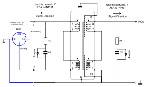
A tuning network is better, but not strictly needed. If RCA is the input, use Ca and Ra. If XLR is the input, use Cx and Rx. LL1527 and LL1581 need only a resistor. The other types need a resistor and a capacitor. Values for C and R are printed on the back side of the PCB, these are just the values from the Lundahl data sheet.

- Order nr: 310-024-89
- Dimensions: 56 x 37mm
Possibilities:
Bidirectional use. Each side can be used as input or output
- XLR INPUT: Probably the most used. Creates a balanced, symmetric XLR INPUT to an amplifier with standard (unbalanced) RCA input. XLR1 (cable shield) of the XLR connector is grounded directly at the connector itself. Normally, XLR1 (cable shield) of the XLR connector is grounded directly at the chassis, or otherwise at the PCB.
- XLR OUTPUT. Creates a balanced, symmetric XLR OUTPUT to an amplifier which has only an RCA output. Normally, XLR1 (cable shield) of the XLR connector is grounded directly at the chassis, or otherwise at the PCB.
- RCA and XLR INPUT in parallel. This is a special case, and interesting application! You can create an RCA and XLR input to the amplifier at the same time. This is nice, when the amplifier already has an RCA connector, so the RCA appearance stays as it was. Connect the additional XLR input connector as under 1). Then, as RCA connector, use an "Isolated Ground" type. Connect RCA center pin to XLR2, and RCA isolated ground to XLR3. Now you have an RCA and XLR connector at the input, where the RCA connector is also "floating" and the ground loop is cut, even when you use standard RCA cable..
- Floating RCA input. If you want to break the ground loop, but not want to use XLR connectors. Connect the RCA side to the amplifier. At the XLR side, the RCA chassis connector is mounted. Use an "Isolated Ground" type. Connect RCA center pin to XLR2, and RCA isolated ground to XLR3. This breaks the ground loop, and may solve nasty hum problems. Breaking the ground loop works only if you do both channels (Left and Right) at the same time.
Grounding of the PCB
XLR1, RCA ground, PCB ground, and transformer case, are the same. (See schematic). The PCB is chassis grounded by the mounting screws. Ground of the RCA side, is soldered with a short piece directly to signal ground. .
Tuning
- If the input is RCA, use Ra and Ca.
- If the input is XLR, use Rx and Cx.
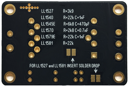
SOLDER SIDE OF PCB. Values of Tuning resistor / capacitor. Without tuning it works also, but high frequency range is 25% lower.
Core |
Frequency Range |
Distortion |
Best Use |
Maximum Signal |
Typical Advantage |
||
Line1 |
mu-Metal |
10Hz-150kHz 0.1dB |
0.1% 9dbU |
Input / Output |
19dBU 6.9V |
High maximum signal |
|
Line2 |
Mu-Metal |
10Hz-200kHz 0.5dB |
0.1% 9dbU |
Input / Output |
19dBU 6.9V |
Higher frequency range than LL1527, and better noise immunity. |
|
Line3 |
Mu-Metal |
5Hz-50kHz 0.2dB |
0.1% 20dBU |
Input |
30dBU 24.5V |
High signal, low cost, low distortion. Can be used also as RCA to XLR converter. |
|
Line4 |
Mu-Metal |
5Hz-45kHz 1dB |
0.2% 22dBU |
Input |
22dBU |
Very high signal. |
|
Line5 |
Mu-Metal |
10Hz-25kHz 0.5dB |
0.1% 22dbU |
Input |
30dBU 24.5V |
Very high signal. Lowest distortion of all. |
|
Line6 |
Mu-Metal |
10 Hz-100 kHz 0.5 dB |
0.1% 3dBu 1 % |
Input / Output |
13dBU 3,46V |
Exceptional good noise immunity. |