
BIASING VAIC AMPLIFIERS
When we sell new tubes we are sometimes asked how to adjust the VAIC amplifiers.
We have to tell this here for for legal reasons:
Some are made by Dr. Kron, some by Mastersound, some by Mr. Vaic personally. So I just try to tell here what I know, but for legal reasons this cannot be an official working instruction. The official bias instruction can come only from the makers of the amplifier. The responsibility for the work done is the sole responsibility of the person who carries out this work, and not with JAC Music company.
- Do not work on the inside of a tube amplifier, when you are not qualified to do so.
- The VAIC amplifiers work at higher voltage than most other amplifiers, and they are most dangerous inside for that reason.
- There is no guarantee that this information is correct
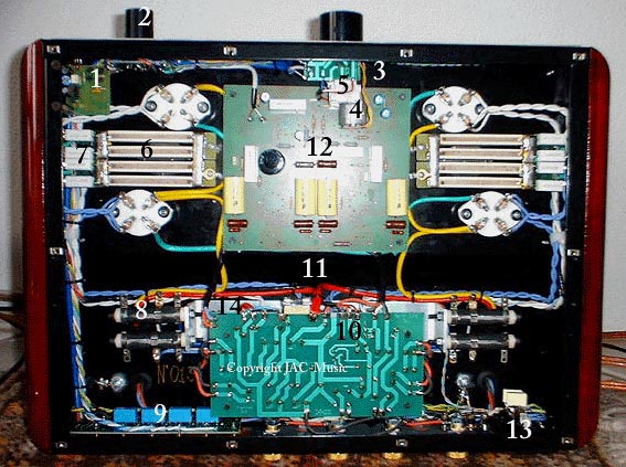
- Remote Control
- Channel selector
- Volume knob
- Motor for potentiometer
- ALPS Potentiometer
- Bias resistors. Measure bias voltage over those. Value is written on them. Here you see four in parallel
- Small resistors for symmetry of heater voltage. HUM POTS mounted on other side of this small PC
- Series Slide resistors for filament voltage, one for each tube
- Relay board
- power supply board
- Fuse
- Pre amp board
- Power input
This is how I exchange tubes myself:
- Always re-adjust the amplifier when exchanging tubes, also when exchanging tubes of the same model and brand.
- Later models have stabilized 5V heaters, with those you need to check if the tubes run at 5V. (If a tube draws more current than the stabilizer can do, it might give not 5V. Older models have the ceramic slide resistors, these are very nice, but it means always an adjustment when you change a tube.
- Possible adjustments, depending on the type of amplifier:
- Plate voltage
- Filament voltages (if you have unstabilized haters). Slide resistors "Nr8" in above picture
- Hum potentiometer (if you have unstabilized haters). Very good hidden, at the back of two very small PCB's (nr "7" in picture).
- Plate Current
ADJUSTMENT PROCEDURE:
- Make some provisions to put the amplifier completely upside down. I tape large pieces of thick Styropor on the transformers for that.
- See if it works at least normally before doing anything with the old tubes.
- Tube replacement is not now yet.
- Switch off the amplifier, short circuit the signal input, and speaker connections, and set volume to zero.
- Check the mains voltage settings. For Europe, use 240V and NOT 220V.
- After adjusting the mains voltage settings, switch on, and wait for normal operation.
- Are the old tubes running at their specified filament voltage?
- Find out, and practice how to adjust and measure the bias.
- Do the measured values make sense? If not, clarify this first.
- Write down the measured grid voltage of each tube. Grid voltage can be measured with a 1000Volts DC scale voltmeter, with the negative lead on one of the two thick pins, and with the other lead you sense the negative voltage on one of the two thin pins. It is somewhere between -70 and -150V. When is measures +600V or so, you need to measure on the other thin pin.
- Set all bias current for one tube to minimum. So the negative grid voltage for this tube is now around -150V.
- Switch off, put in ONE replacement tube, switch on.
- Measure quickly the filament voltage. If wrong value, you must adjust it, as quick as possible. If slide resistors, switch off the amplifier. Do not slide those with the amplifier on. Overheating with more than +0.5V is damaging the tubes quickly.
- Adjust the bias. Most 300B amps have 21Volt across the bias resistor (number "6" in above picture). However, you need to find out the right value yourself, by using Ohm's law.
- The plate voltage is measured between one of the two thick pins, and the other lead on the thin pin that has around +500V. From this can be calculated the tube dissipation. Recommended is:
- 22 Watt for EML 300B-Mesh
- 28 Watt for EML300B or 300BM+
- 33 Watt for EML300B-XLS, EML300B-XLM. AVVT 32B
- 35 Watt for EML320B-XLS,
- 39 Watt for EML520B-V2 or V3,
- 48 Watt for EML1605.
- After this, check the filament voltage again, and re-adjust if needed
- In case you had to re-adjust the filament voltage, you may have to re-adjust the bias again. Repeat, until both need no change any more.
- Repeat the steps for the other output tube.
- Now let the amplifier run. Continue for one day, check the bias every hour and readjust when needed. Don't focus on fine adjustment, just correct changes of 7% or more. Micro changes will appear all of the time, causes by changes in the mains voltage
- At the end of the day, when still warmed up, do the final adjustment. Try to find a moment when the mains voltage is at 100%. That is mostly in the evenings.
- Now, the bias is done. Switch off, connect a sound signal, and speakers.
- If you know where to find the hum pots, you may need to adjust those too, because often they were set wrong by somebody.
- Let the amplifier run on your HiFi System now, to burn in the tubes.
- After some days check the adjustment again, at a moment where the mains is at 100%, and when all ok, the work is done.
- Write the final bias values on a small paper, and put this somewhere inside the amplifier. Some day, somebody will be happy with those numbers. You would have needed those at point 7) above here.
PLATE VOLTAGE SETTING. Some amplifiers have the option to select two or three plate voltages. In older models this is done by soldering off a wire from the edge of the power supply board, and connect it to the adjacent solder pad. Later models have a link that you unscrew set to another position. So it is a three position switch, but for operating it you need to unscrew the link. Take low plate voltage for 300B, or 300B-mesh. Medium is for 300B-XLS and 320B-XLS. High is for 520B and 1610. Also by this method you can operate tubes like 520B-V3 in a normal VAIC 300B. They were made for this, and it is the purpose of this switch.
CONCLUSION FROM THIS TEXT: If you have more questions after reading it than you had before, then my strong recommendation is, find a local tube specialist. The VAIC amplifiers work not so difficult, but they work by a little unusual concept, and are not really self explaining for a beginner. Also I cannot change a beginner into a specialist by answering questions by email. Getting experience takes a few years time.
ATTENTION! THERE IS NO WARRANTY OF ANY KIND WHATSOEVER IF YOU USE THIS PROCEDURE YOURSELF. THE ABOVE IS ONLY HOW I PROBABLY WOULD DO IT MYSELF WHEN REPAIRING A VAIC AMPLIFIER.