Repair of a Heath kit IT-28 capacitor checker, and some advise on testing capacitors.
About this IT-28
I bought this Heathkit IT-28 on Ebay for 164 Euro. The seller set a check at Ebay at: 'Used but good condition and fully working'. Then in the description he writes he could not fully test it, and with a 100% positive feedback profile, I took my chances, being prepared to overhaul it anyway. When the item arrived, OF COURSE it was defective. Ebay. It took me one evening to overhaul it completely. It were just old age problems, and I have it now on the bench perfectly working and calibrated.
Keep in mind, high voltage components costs money, and (good) designers don't take such without reason. So in reverse, when you see a high voltage capacitor in a circuit, it needs to be tested at high voltage, because it is there for a reason.
What IT-28 can be used for
actually it is a very nice tester, and it can do a lot. Precision is even quite good, because it has a Wheatstone bridge inside, which is balanced with an AC frequency. Though this precision is not even necessary for most capacitors you are going to test.
First, let's see what makes sense to do, on the repair bench.
A capacitor model, which contains all the parasitic elements, is very complex, and in school they like to annoy students with it. In real life, at the repair bench, after testing a capacitor, all you need to know is, where to put it afterwards. That is In the waste basket, or back into the equipment. Most problems of course are with electrolytics. Also most of these 'problems' are only caused by very long switch off time, and this is reversible in many cases, IF you do it the right way. The advantage of this is quite a few. Your equipment is in more original state afterwards, but also sich high quality capacitors, from Sprague, or other fine companies, if still perfect after 60 or more years, I trust them more are China made replacements. The craziest thing would even be to replace vintage tantalum wet capacitors (which last for ever) by Aluminum capacitors from China. I replace only when capacitors test also bad after re forming, and that is not many cases.
What causes permanent damage to electrolytic capacitors?
Problems are in this order:
- Exceed maximum allowed AC ripple current. Really some designers never heard of this.
- No significant DC voltage across them in the application.
- Cracking of the rubber seal (where the wires comes out)
What causes reversible damage to electrolytic capacitors?
Problems are in this order:
- Long time storage, without any switch on.
- DC voltage in the application is always very low
If old equipment was switched off for decades, most capacitors will test not very good any more, and the infamous re-capping begins, of which people are always very proud. However in very many cases, such capacitors need only a re forming, which is the same process as in manufacturing, right after they were made. The only thing we need, to make re forming possible, is the capacitor is not damaged. Which is very likely the case, when the rubber seals are not crumbling, and when they were good, when equipment was used for the last time. Damage may occur when you simply switch on old equipment after 25 years, to see what happens. So with brute force, skipping the re forming process. That may give capacitors a final blow, and if that happens, it damages other parts of the equipment as well.
The humidity is one thing, it concerns most parts, also film capacitors. Another thing is the change of the isolation layers inside electrolytic capacitors. They are not called electrolytic for no reason. Initially, when they are made in production, there is not much of an isolation layer in between. There is only the paper, which is soaked with a mild solution of acid in water. So, wet capacitors. Then when voltage is applied for the first time, the aluminum with the acid, begins an electrolysis reaction, which produces an isolating layer of aluminum compound. This process uses some current, which may seem leakage, but it is not that. Once the layer starts to build up, isolation gets better and better, until finally the current stops to flow. Even with wet acid in between, because the layer is none conductive. Then, the voltage can be increased, and the layer breaks down. This effect however causes current, and the layer self repairs, and gets thicker and thicker. This can be continued until the physical limit of the thickness is reached, and the capacitor will then be above it's rated voltage even.
So what causes the damage?
Very simple: The forming process reverses by itself, it is just a matter of decades. If the equipment would be in use regularly, this doesn't happen of course. Though we will see here, the capacitors remain only formed at the voltage they were actually used at. This is not a problem at all, but when testing such a capacitor, of course you will see it can not do it's rated voltage any more. Once it was removed anyway, just re form it to the rated voltage, and it will make the capacitor last even longer as it did already so far.
Just as an interesting remark, I have still in use on my office here, the FM radio of my grandfather, which he bought new in 1960. I see no reason to open it up. It works still fine, but I make sure it gets switched on regularly. Same for my 1955 Hammond Model B3 organ, it has all original electrolytic capacitors still in there.
What is forming?
If the isolation layer of electrolytic capacitors has partially disappeared, the capacitor will start to become conductive somewhere at 40...60% of the rated voltage. If so, it behaves like a Zener diode. When this voltage is exceeded, it pulls a lot of current. When it is reduced, the current disappears again. While testing, It seems as if a 500V capacitor can only do 200V. If you simple connect 500V to it, it will pull a lot of current.
In such cases, the capacitance has increased, which is normal, because the isolation layer has become thinner. If you see that, the capacitor is FINE, it just needs a new forming. Ignoring this, so simply force 500V on it, by switching the equipment on, will cause a very large current, making the remaining isolation layer suffer. On the one hand, this quickly builds up a new layer, but such a layer is not the best quality. It should be done without large current, to prevent crystal building, and to prevent outgassing. (Same as when you overcharge a battery). This is what a good capacitor tester can help you with, also the IT-28. Well, the only thing you need to to, is slowly increase the voltage, and wait with the next higher voltage until current drops (That is when the magic eye opens again) . Or, apply the maximum voltage right away, with an external current limiting resistor in series. Also here, you can look at the eye for this.
With potentially good equipment, which was only switched off for a long time, it pays off very much, BEFORE switching on, to check the wet electrolytic capacitors one by one, and if needed, re form them. That will work out nicely most of the time, and the equipment stays more original. Myself I would not buy a 're capped' instrument, when all (probably still good) original Sprague USA capacitors were replaced by modern junk from China.
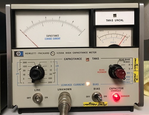
A more professional tool for re forming, is the Hewlett Packard 4350A. (See below here), but the IT-28 does this just as good.
After the forming was done, we can begin to measure. If you skip the forming, you will soon have a large waste basked with supposedly bad capacitors, which were not bad at all.
What can be measured? Well, not just the capacitance, because that can even go up, while quality has gone down. So how to determine it's quality?
A capacitor has a parallel resistance, called leakage resistance, it has a series resistance called ESR, and of course it's capacitance. Sintered (dry) electrolytics are usually just very good or very bad. The rest is about Wet Aluminium capacitors. These are not a bad as their reputation, it is just they have limited life time at very high ripple current, and their shelf life is no very long. The leakage resistance of a wet electrolytic is low, as long as you are very far away from the maximum working voltage. However at some point (usually 60% of maximum) they appear to develop large leakage. But is this really so? No....probaby not! They just need re forming, and they will be fine again for decades. It would be a mistake to throw out such a Sprague USA capacitor, and replace it by China made junk, just because you never heard about re forming.
Leakage can be measured at D.C., and will vary with the voltage, depending on the properties of the dielectric. That is why some capacitors will measure good on a Multimeter, where the test voltage is low, but appear leaky at a higher voltage.
ESR means Equivalent Series Resistance. This is based on the idea that a practical capacitor can be seen as a capacitance, with a resistor in series. Such a measurement gives you the series resistance and the capacitance.
Mica, plastic film, and ceramic capacitors have very low ESR. Paper in oil caps when new have low ESR, but they can show random leakage, which may come and go.
Cheap Chinese ESR testers are getting better every year. They based on a software, a Danish engineer posted on a forum as freeware. The Chinese said thank you, and developed it further. I saved this communication on my PC when I saw it passing by on a forum! These devices charge and discharge the capacitor, which curves unveil it's electrical data. This works nice for larger capacitors, and such which have no curious faults. So just wear out. What these can not do, is give a good answer when the capacitor is just a bit flaky. They become quite un precise at low values however. Imagine to sample the charge time of a 10pF capacitor. Most all, they can not test at higher voltage than the battery voltage. This means they can NOT test high voltage capacitors reliable. Yet I agree, these are very nice tools, and they are the most used one my bench as well. Also interesting, these work at such low voltage, that semiconductor junctions do not work yet. This means often you can test the capacitor directly in the circuit. If it appears to have high ESR, that's what it has. If anything is in parallel, it messes up the measurement, and results will be odd. So only then you need to remove the capacitor from the circuit. This advantage is really great.
Dissipation Factor, also just called 'D'. This puts series resistance and the capacitance in relation with each other, which make a lot of sense. ESR of small capacitors is always higher of course. So ESR by itself, it is a meaningless number. Now, for the ratio, we need actually the REACTANCE of the capacitor, which is nothing else but the resistance is appears to have at a certain frequency. So instead of capacitance, we use reactance here, and this (resistance) we put in relation to the series resistance. For a 100uF or 1000uF capacitor of the same series, it would be the same value. Indeed this indicates also if there is power dissipated on the capacitor, which of course is something we do not want. An ideal capacitor has only capacitance, no parallel resistor, and endlessly small series resistor. This gives a phase angle of 90° between current and voltage, so it can not absorb power, and will not get warm from ripple current. A very good practical value is D=0.01. Not so if the dissipation factor goes up. The higher it becomes, the more loss is generated in the capacitor itself. It gets warm for that, but also does not do it's job in the circuit very well. The quality factor is just 1/D. So when D is low, quality is high.
Power factor (PF) expresses if the capacitor uses power. This heats up the capacitor, making the problem soon go worse. If PF=1 current and voltage are exactly in phase. An ideal capacitor does not absorb power so power factor may be an indication of resistance in the capacitor.
There are many other properties of capacitors, but only to pick out the bad ones, we don't need to know those.
industrial LCR testers are an alternative, which do an excellent job, but they are costly, and most of the time do not have the capability to test under high voltage. Which is however needed when a higher voltage is printed on the capacitor.
Hewlett Packard 4350A. This a Capacitor tester which I saved from the scrap when I worked at Hewlett Packard. It still works good, but lowest is 1uF full scale. But for that it can test up to 300.000 uF. It can do maximum 100 Volts bias, or up to 600V with an external bias supply. I tried this with plastic gloves on, and it works, but I don't want to do that any more, it is just too dangerous, hooking up 600V up to this item with an external power supply, and you don't really know how it can go wrong.
About the danger of this. You see the talk about lethal voltages, on DIY websites and perhaps you don't even read it any more. Let me tell you, I once had an Electro shock of 830Volts DC, by merely tipping only my finger on a tiny screw of a plastic dial knob which had this voltage on it by mistake. It was while setting up a similar measurement with an external voltage. So this 830V was on the chassis of the equipment, and I knew that. But I made a mistake, not expecting a metal screw on that knob. (It was not with this HP Meter). You would perhaps think I would only say ouch! and my finger hurts a little bit. Well I had a blister on my finger tip indeed. Also an severe contraction of every muscle in the body, down to my feet. My leg muscles were painful afterwards. On my head, the best description is like a crocodile bite the skull. It felt like BANG! I fell backwards off my chair, but not unconsciousness, and I was very lucky my heart survived. I could not work for three days after. Looking backwards, I suppose the current went trough the spine, in my shoulder region, which fired this reaction of all muscles all together. Anyway, I learned my lesson, I really did.
An vintage LCR bridge, is the unbeatable lab instrument. Their price is low. It is silly, but when it comes to tube testing, people that know very little about it, LOVE lab instruments, which exceed their own knowledge by far. They would be far better off with a good tube checker. But when it comes to capacitor or inductance testing with a lab instrument, they are interested, and want something more simply. So take your chances, and you can find some beauties for only 30 Euro :)

This is my French LEA bridge. I bought it in 1987 on a scrap auction for 15 Euro. This is a miracle of precision, and I use it always when I need reference parts.
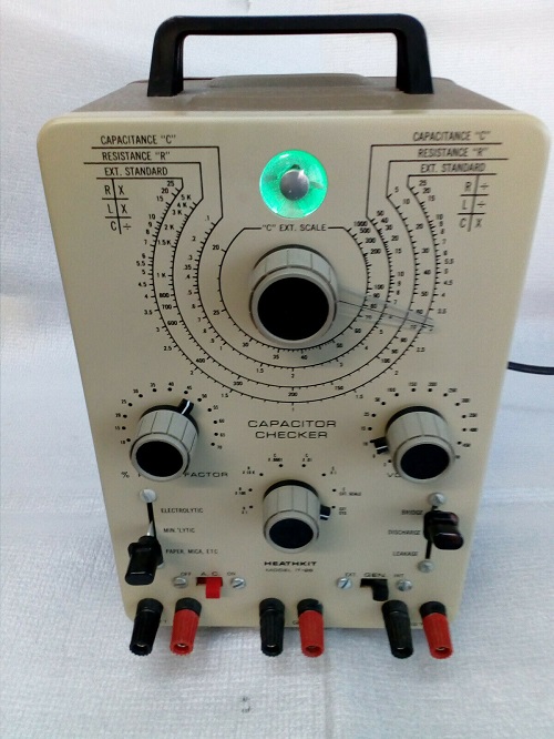
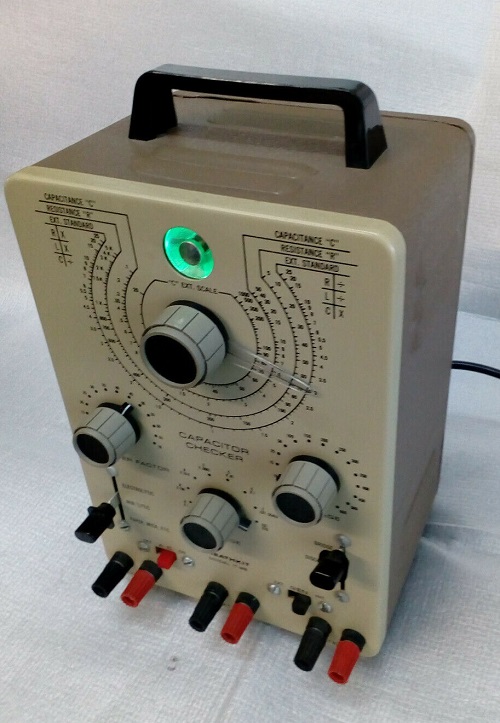
The HEATKIT IT-28
This is called a capacitor checker by Heathkit, which word does not do justice to it. Inside is a classical Wheatstone Bridge, just not with lab precision like the one above. It does indeed have all the possibilities and connections of a real LCR bridge, and frankly precision is not bad at all. When I take two 5% 10k Ohms resistors just from my parts, I can take the one as a 'reference' and the IT-28 will say the other is 3% too high. When swap the resistors, IT-28 will say it is 3% too low. You see...It works :) That would need an expensive Fluke multi meter to do the same. But when you do this with capacitors, you can actually do the same measurements, and the Fluke can not do that as good.
People are raving about the IT-28 on youtube, and they are right. It's only a capacitor ''checker', but it's precision is very good, and it tests capacitors from 10pF to 1000uF. You can go marginally below 10pF even, by adding 5pF in parallel to the tester, and subtract 5pF from the result. For larger values
When it's just for repair work, you only need to know if the capacitors are good. So little tolerance, no leakage, low ESR, and no parallel resistance. Specially since parallel resistance and ESR are not specified anyway, there is no use for difficult measurements, and in the end I have nothing to compare any ESR values with. So what those 15$ Chinese LCR testers are doing, is good enough for me. Only here comes the problem, charging and discharging is not the same as really measure capacitance, because discharge results get impaired by any fault resistance, in case the capacitor is bad. So these Chinese testers are fine, as long as you test good capacitors with it. When the capacitor has some problem, you can not trust those testers any more. Besides they can not test leakage at high voltage.
The result of the IT-28 is just what I need. It works not as fast as a Chinese tester, but fast enough, and I can see exactly what it is doing. Precision is good enough for me. So when a capacitor has 22uF printed on it, and it tests 25uF with 3uF tolerance, it satisfies my needs.
Leakage testing
After this, comes a great aspect of testing with IT-28, you can do a leakage test at any voltage from 3 to 600 Volts DC. The test is current limited. So when a 500V capacitor is stored many years, it may at fist refuse to go above 250V, even when you set the test for 500V, it current limits at 250V, until the capacitor begins to accept it. Or, it doesn't and then it's defective of course.
You need to balance the bridge until the eye tube opens. This is not going to happen when the capacitor has parallel resistance. Tantalum caps can have this.
ESR testing.
When you find the value at where the eye fully opens, as a second step you may do, is a power factor measurement. I do not know exactly how they did that electrically, but the power factor is simply: The percentage of the Capacitor Impedance, which equals the ESR. (Equivalent Series Resistance). So ESR is something which can only be indirectly measured, and it is an imaginary series resistance if the capacitor, which appears in AC operation. An ideal capacitor has zero Ohms ESR, which already makes it clear this can not be directly measured. Yet when I send an AC current through a capacitor, I do not expect it so absorb this current in the form of electric loss and heat development. I expect zero loss, ideally. Such a capacitor has a zero % power factor. If it absorbs however 10%, that means it has some noticeable ESR. But easier is to say, it has a power factor if 10%, and this is the IT-28 approach. If course you can quickly calculate power factor into ESR and vice versa. ESR equals the Impedance of the capacitor at 50Hz, times the power factor. Very simple. The impedance is at 50Hz, because power factor is measured at 50Hz as well. in 60Hz regions it works just the same. It doesn't matter and you would find the same ESR.
So when the impedance at 50Hz is for instance 100 Ohms, and the power factor is 5%, the ESR is 5 Ohms. I have one of those cheap #Chinese testers, and they give also ESR of course. The problem for me is, I have difficulties interpreting any ESR value, because you have to relate it to the capacitance, and look into the manufacturer data sheet, or some 'rough' tables you find here and there.
Not so with the power factor. The lower the better. It is simply in percent, regardless the capacitance. The following I learned quickly from working with this. I found the power factor to be 5...8% for an old fashioned, relatively large dimensions electrolytics from the 1970's. I have several in my junk box. They're not bad at all! Comparing those with the newer types which are unbelievably small, and very high voltage, show those newer types have twice the power factor, so twice the ESR. So a small size, is definitely a big disadvantage if you want low ESR.
Work done with the overhaul if the IT-28.
This text may be some help for your own restoration.
The power Supply caps, one was bad. I exchanged both with two NOS capacitors by Cornell Dubilier, from 1940! Same value, same size, same appearance with paper sleeve, and perfect condition after I re formatted them carefully. Due to the nature of those (same ESR....) the test voltages, are EXACTLY as written on the switch. There are two 40uF caps is series, without balancing resistors. This will work, as long as the device is regularly switched on. Other as people think, voltages balance up nicely, because there is also AC signal, and AC current, and ESR, and the capacity is the same. The problem is another. If switched off for 1...2 years, like all caps, they begin to loose their formatting, and likely in a very unequal way. So they will refuse to accept 300V quickly, and only charge up quickly to 150V. Then at that voltage, they develop a 'battery' nature. As if you charge that battery. So they begin to pull current, only for themself. And very slowly, the voltage begins to rise. This will continue up to the applied voltage (here 300V per cap). Depending on how badly they needed the formatting, this can take 2 seconds, but also a minute. (Doing it ideally right, would take hours). At a repeat they will immediately accept 300V. A problem comes however, after longer switch off period, when one tries to pull 5mA at 150V, and the other pulls only 1mA at 200V. The 1mA cap will be quickly charged at 300V. However the other will see only 1mA, because they're in series. So not much change will happen to it. It needs 5mA. The power supply is 600V however! So the good cap gets charged much over 300V. Also far above, until it reaches a painful limit, somewhere around 400V and begins to pull current (and begins to dry up from this). It is from this excess current the other cap gets finally formatted, until it comes closer to 300V, and the of course the good cap gets closer to 300V as well, and the whole thing comes at rest. That was a very bad cycle. Though at a repeat it will not happen again, this did pre-damage for the next time you try it, and one day it ends up with bad capacitors, because 'the device was switched off too long'.
All in all this is a design mistake, and all people say they found bad caps inside. A balancing resistor directly over the caps however, must be able to take a few mA, otherwise it doesn't do it's job, but that would drop the voltage. Any very high resistor values are useless. A better solution would be a Mundorf 20uF 700V 'tube cap'. Well so far the NOS Cornell Dubilier I used, do their work, but if they damage after all, I replace them by a tube cap. Alternatively replace the 6X4 tube by a silicon diode. This will boost the output voltage somewhat, and now there is room for some voltage drop by two balancing resistors. I would leave heater burning, so the transformer keeps seeing the same load, and output voltages stay unchanged.
The switches. They were treated with contact oil, the aggressive kind with acid residue in it, which is typically used for cracking potentiometers. As always, this created some black smear compound with the silver oxide, and made it all worse. Remarkably, this smear solved perfectly in isopropanol alcohol, and the acid had nicely cleaned the silver underneath, and it appeared shiny like new. What is harder to remove is the acid which has soaked into the wafers, but let's not hope for the worse, and just clean it with an alcohol bath. Isopropanol is not like "normal" alcohol, it smells the same, but it is a little bit aggressive against paint and plastics. The wafers will appear free of leakage later. So now with no smear or whatever on the contacts, it worked perfectly. Silver is self cleaning, and needs no lubricating.
The pot meters. They had no good contact any more. I guess one's first approach may be contact oil, but that helps only for a year or so. They can be opened easily, just take off the cap. Inside was strange substance, the remains of what must have been grease. That solved also in isopropanol alcohol. Since obviously this metal needs lubrication, I used some silicone fat, and the pot meters. work like new again. These potmeters are excellent quality. Leave the old ones in! In case the main pot meter is worn out, you will have a hard time replacing it. You can exchange it with the power factor potmeter, it is the same! This one is not really dependant on the right working angle, and you can replace it with any good 1000 Ohms wire wound potmeter.
The 6.3V to 12V transformer. It is terribly noisy, but good. So I left it in, but the IT-28 is quite loud because of it. I may fix that one day, I need to mold it in two components resin.
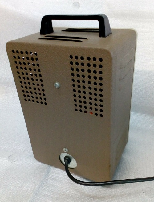
The case. Some fool tried to open it from behind, which is impossible. The scars could be flattened with a wooden hammer.
The soldering and wiring. Many confirm terrible experience here. Some say they all have at least two bad solder joints, and 50% of the Heathkits have at least one wire connected wrong. My builder did a good job. This man could solder perfectly well, and he laid all wires nicely together in groups. Even nicer as I would have done myself. No error, and ALL solder joints are good. Also I found the main scale was calibrated perfectly.
Conclusion
Precision is very good. ESR result is roughly the same range as with the Chinese tester, though differences are 30 to 50% sometimes. I trust the IT-28 to be right.
Sensitivity is a a dream. The lowest range is 10pF and it can REALLY do this nicely and precise, so keeping apart 10pF from 11pF. Amazing! This is really a very nice tool, and I understand why the price for good one is so high on Ebay. I do not want to miss it any more!