Since 1993 Copyright Notice
About Selenium Diodes and Copper-Oxide diodes in old instruments.
Discussions about opinions
You will read in the forums, that old Selenium diodes are dangerous items. Experts tell you, these can unexpectedly get defective, and spray poisonous substances in your direction. This seems to happen mainly to those people writing these warnings, but it never happened to me. I have seen many of those diodes. Initially I always thought when I see those cooling plates, it must be one of those poisonous devices. But many times they were actually even the older Copper Oxide diodes, which are not poisonous at all. I wonder how many good working copper-oxide diodes, have been replaced by replacement circuits, on the advise of the expert writers. And then guess what they did with the "poisonous" object, they just throw it in the dust bin. Who cares. Such a replacement, not very important for circuits needing indeed just a diode only anyway. But it will impair good functioning of instruments, when the forward voltage, reverse leakage, and a few more things, affect the calibration. It may do the trick probably to re calibrate the instrument, but not always.
Just to give you an example, the greater part of available diodes show no function below the threshold voltage. A germanium diode, is a difference species. It has not a threshold voltage. It is a diode at any voltage, even at 1 mili volt. Just at higher current, this 0.3Volt forward voltage develops, t you can as well rectify a 1mV signal with it, as long as you load the resulting DC voltage with a high impedance. You can't do that with a silicon diode. Below 400mV, it stops working totally.
Before semiconductor diodes, we had already metal diodes. The semiconductor was invented long before the Germanium diode. It's also two layers. A metal diode is not something inferior. They have disadvantages but also advantages. In the range below 0.7V a metal diode is much superior to Silicon, and not just a little bit. A silicon diode is "dead" below it's threshold limit, but a (single cell) Metal diode begins to work much below 0.7V already. If loaded with a high impedance, they do a much better job, like for instance in a voltmeter. A replacement for a low power metal diode is a Germanium High Current diode like 1N93, with a series resistor connected to it. However Germanium is too good, because at low current, they work stil below 0.3V, which a metal diode CAN do also, but not as good. Consider simply replacing a broken Selenium diode, with another good Selenium diode. They're not impossible to find, and even still made (when I write this in 2026) for replacement purposes. Also, Selenium diodes have one very special property where they outdo Silicon by far. They are extremely resistant against short overload. Unlike a semiconductor, which after an overload must be considered unreliable. For such applications with excessive peak current, selenium rectifiers are still made, because they are more reliable. That is quite something else as "bad, dangerous" devices.
It is very strange, but anything having to do with diodes, is a field where amateurs feel competent to advise newbees. I stressed this point at some other places of this website, when using vacuum tube diodes, where we see the same thing. This becomes more difficult, as reading data sheets is regarded a waste of time by this group.
Forums are nice on the one hand, but generally it goes wrong when it's just gut feeling what they are writing about, but pretending to be specialists. Go to any forum and ask for sound difference of Chinese 300B vs. genuine Western Electric NOS 1930. You will quickly be advised about "sound" by people who only know about Western Electric 300B from internet pictures. But they will tell you how it sounds. Think about that, before you believe it.
For replacing Selenium diodes, it's exactly this kind of "knowledge", you must take not too serious.
Some (partial only) rectifier history
Before electrical diodes, there were a few way to rectify AC voltage. Like a fast polar relay, or an AC motor, driving a DC generator. These could be constructed on the same axis. So just a box with something rotating inside, and it would converts any AC or DC voltage into another DC or AC voltage. Also an interesting item is the wet diode. This is nothing but big plates of metal, in a conductive liquid. WIth one plate of lead, and the other of aluminum, it becomes a semiconductor. Clearly, with the liquid, this can never become a high voltage diode of course, but for very low voltage, like 6.3 Volts, at high current, these worked good. It is perhaps forgotten a little bit, but before the gasoline engine was invented, the streets of New York were full of electric cars, using at home such rectifiers for charging. This whole hype of electric driving, we had it in the 1880's already. It was obsoleted after the gasoline engine was invented.
When was a kid, I remember the speed of the merry-go-round, was controlled with a huge electric cell. This was a water bath of 80x80 centimeter, and very slowly, metal plates were dived into the liquid, with a handle. It looked exactly like a big variable capacitor. The operator would slowly sink the plates in the liquid, and while the merry-go-round would pick up speed, the liquid began to boil. Kind of primitive, but it worked perfectly, and there could be nothing wrong with it. Just add some new water.
The crystal rectifier, is quite the opposite. Delicate and only capable of low voltage, low current. It was discovered in 1874 by the German Professor K.F. Braun, a wireless enthusiast and Nobel Prize winner. A semiconductor effect was already found with crystals of Zinc Oxide, Copper Sulfite, and a few others. In 1878 Werner von Siemens discovered the Selenium diode. However it resulted from his interest to make photo detectors. It would take another 50 years (!) before Selenium rectifiers as we know them, were coming on the market.
In 1925 came the Copper Oxide diode, which look like stacked coins. These are made by copper oxide on one side of a copper plate, and then add a conductive layer over the oxide. To make them work good, it required copper with a very low oxygen content, which is hard to get, and normal electrical copper can not be used. In addition, specific impurities of the copper were needed, and also the lack of some others. This was one of the things, which made those so difficult to manufacture. It appeared that Chilean copper was the best, and some other copper could not be used at all. The tragedy of the Copper Oxide diode was, the fine details of the process were kept secret, just the things everybody could find out were patented. This has always been the tragedy of a special process: You can patent it, but then 25 years later, when the patent runs out, while the patent papers are a free guideline for anyone. Or, you keep the tricks secret, and you can use it as long as you want. For Copper Oxide diode, a mix of patents and secrets were used, but it means today, the secret part is lost, as the people who di know, refused to speak about it, until they died.
Moreover, the temperature at which the oxide layer is grown is around 1000 degrees Celsius, and must be kept very precise. The speed of the cooling down process , influenced the impedance. Meaning, if the copper was cooled down slowly, the break down voltage was higher. If cooled down fast, the break down voltage was lower, but such could tolerate higher current. The Selenium diode had a much easier production process. Copper oxide diodes were only used for applications where low forward voltage was desired. Such as in AC voltmeters. In terms of the "best" diodes, Copper Oxide is better than Selenium. Just Selenium is incredibly tolerant against surge current, outdoing silicon by far, even today. Also Selenium is lower cost to produce, and no production secrets. So it was no wonder, Copper Oxide diodes disappeared. If you find one in an old piece of equipment, you are looking at something, which today nobody could build any more.
The Selenium diode was invented already in 1928. Even though when easier to make as copper diodes, production was still a recipe, of the small additions to the Selenium layer, combined with several process steps, some under high pressure and high temperature. This created the desired crystal structure, for getting a low series resistance. As a final step, the reverse voltage is increased by a forming process which takes place under heat as well, with electric pulses. The resulting Selenium plated metal sheets, are relatively robust, and can be stacked easily, after which the diode is sealed with paint. Old data books write 60.000 hours life time, which was much better than any electron tube. Besides Selenium diodes could be stacked to any desired voltage, or be made as large as needed, to get any desired current rating. .
Today's applications
 Selenium diodes are still made by a UK company, called gdrectifiers, and also by a USA company called Cougar Electronics Corp. The UK company says they build those are replacement parts for old equipment. The USA company goes one step further. They say, their Selenium diodes are self recovering even in case of extreme surge current, whereas silicon will damage permanently, at much lower surge current. Also Selenium cells can be used in reverse at their breakdown voltage, as long as maximum heat development is not exceeded. This is also something you can not do with silicon diodes. Unless it's a Zener, you can not develop maximum heat at breakdown. So Selenium diodes are robust, hard to destroy, self recovery parts. It sounds weird, but they advise Selenium diodes for high reliability applications. Another application is for high energy surge protectors. Like 10 Selenium diodes in series would for instance have a forward voltage of 250V. Any voltage above that gets brutally clamped, with extreme surge currents possible, because such devices are big size, and the diodes have a large surface. So unlike with the PN junction of a semiconductor, the heat is generated at the surface of a thick metal plate.
When is an diode ideal?
That answer can be given quickly. At the rated forward current, it has no forward voltage, and in reverse condition it has no capacitance. That would be ideal. Unfortunately, this doesn't get us any further :)
For small power supply applications, today's silicon diodes are close to ideal. You can buy such for 1 cent, which have a peak reverse voltage of 1000V, and forward voltage of 0.7V at 1Ampere. Just the larger types, so 50 or 100's of ampere are very bulky, and get very hot. So, not really ideal, but still very good.
For RF applications, we need them with low capacitance. Such exist, but the low capacitance comes from small chips, with the drawbacks of higher impedance.
Specifications
Selenium Cells were made, ranging from 50kV reverse voltage, 5mA forward current, to 50V reverse voltage, and 100.000A forward current. The voltage specified, in old data books was usually the RMS Mains voltage. A single cell is marginally above 20V. So to rectify 117V AC in the USA, it needs 6 cells. Yet one "20V" cell has a breakdown voltage of 30V.
For small signal applications, it becomes more difficult to understand.
Here, the diodes are usually intended for changing AC voltage to DC. WIth large signal that is easy, but how will you rectify a 20mV signal? This can never be done with silicon.
Myself, I have several pieces of old equipment with Selenium diodes, and they all work good. Initially I was reading the forum babble too. So yes, I wanted to replace those bad, dangerous, poisonous, and unreliable items. But with instruments, of course the meter scale, and the whole functioning takes into account what curves Selenium diodes have. So there is quite some risk to compromise the quality of the instrument.
So looking into curves of Selenium diodes, I can only say, those curve were always EXCELLENT. Though these Lucas branded, early type silicon diodes, in the AVO Mk4, I sometimes had to replace.
For small signal, Silicon diodes are the worst choice. To understand this better, throw overboard all that forum babble, you are probably infected with that as well. Of course it has to do with the higher forward voltage of Silicon, but that is not the real issue. Germanium has not only a lower forward voltage, but unlike Silicon, there a rectifier function BELOW the forward voltage as well. And not just a little bit below, but at EVERY voltage. That is why you can use a Germanium diode, to detect (and rectify) a signal if just a few millivolts. Whereas a Silicon diode is simply dead below 0.4 Volts.
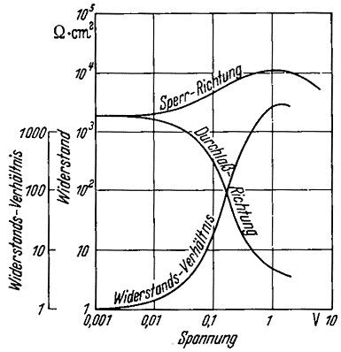 Here comes a good thing with Selenium. These diodes have this interesting property as well, to begin working much below their rated forward voltage. To rectify small signal, this makes them very good as well. Not for radio, because of their capacitance, but for AC voltmeters they are ideal. Not as ideal as Germanium, but quite close.
Rectification begins when the forward resistance is lower than the reverse resistance. From this graph, it can be seen, this begins at 5mV already. With Silicon this is fully impossible, it has no significant forward resistance below 0.5V.
Selenium diodes are just two metal plates with some Selenium composition in between. And voila: A real semiconductor, and a good one! Only maximum reverse voltage is not very high, but resistance is much lower than vacuum tubes. You can even take them apart, there are dark layers on the metal. Pile it back together, and they still work. I tried that with an old Siemens Selenium bridge rectifier. I do not intend to do so with my AVO (Made by LUCAS) diodes. But the simplicity of such diodes is amazing.
It's just there is a high voltage drop at high current. We all know that. So though they appear low voltage, high current, if compared to vacuum tubes, they do get very hot at high current. But what happens at low current? They do not get hot, do lifetime expectancy is good. There there is no large voltage drop any more, and here comes the advantage vs Silicon: So no voltage drop, and they work already at very low voltage.
With Silicon diodes, if you want to use them a little below 0.7V you can do so, but current flow will be small. You can increase the current flow by putting several in parallel, this needs no explanation. But a quicker way to achieve this, is using a very high current Silicon diode. Like a 6 Ampere diode, and use this to rectify small signal. This is exactly why you will find such (6A) diodes in parallel of the meter of the Mk4 tube tester, to protect it. (And not a small signal diode, as the forum babblers will suggest you).
The Copper Oxide diode of the AVO two panel tester, is not used to protect the meter. This meter is not very fragile anyway. It's purpose is only to generate the negative grid voltage, for the "set zero" knob. It means, in this tester you can replace it by a Silicon diode if needed, and when the Selenium diode seems to work good, you can just leave it in.
This Silicon Diode (I have the red and black leads attached to it) was used by some repair man, long ago. It is one of the craziest repair job I saw. It was an historic AVO "two panel" tube tester, which I bought om a radio ham show. The diode in the picture, was to repair this supposedly bad LUCAS Copper Oxide diode. He let the copper diode in, with the leads soldered off.
The forward voltage of the LUCAS diode is appr 1.4V at small signal, so replacing it could be by two silicon diodes in series, and that's all you need to do. Now believe it or not, in the AVO tube tester, where this LUCAS diode belongs inside, the man reversed the panel meter by mistake. So the needles moved in the opposite direction. Now he noticed that also, but he thought the problem was somewhere else. He swapped several other connections too, as these were obviously soldered in "wrong", by some fool he must have thought. After doing so, the device worked almost. Just the diode of course, it did not work, because he would have had to reverse it also. But he did not do that, he concluded the diode was "bad". So he replaced it with a silicon diode. He happily put it back together and the tester worked well, and he used like that for decades. Myself, when I bought it, I wanted to clean meter glass and scale. Then I found out the meter was put in reversed. I had of course the same strange experience, some parts were mounted reversed. And they were! Believe me it took me some time to understand this mess, and repair it all back to normal. And then, the "broken" Copper Oxide diode worked again.
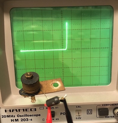
 It was nice of him, not to remove the "bad" Copper Oxide diode, but when I connect it to a curve tracer, there was nothing wrong with it. Indeed after re connecting everything correctly, the tester worked normal, with it's original Copper Oxide diode.
Take good note here, the scale of the HAMEG Curve tracer is 3V per division. So the Copper Oxide diode as well as the Silicon replacement diode, have 1.4V forward voltage. Unfortunately I lost the Silicon diode, but it was a LUCAS High Voltage diode, with two diodes in series, in one epoxy housing.
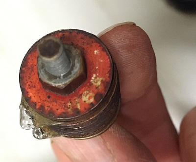
This is the old LUCAS Copper Oxide Diode of the AVO Two Panel Valve tester. I believe the same are in the AVO Mk1 and Mk2. (Very well hidden). At least they look the same.
Texts have come off a little bit, but the readable part is: .../6A. It is much too small for 6Ampere, so 6A means 0.6A here.
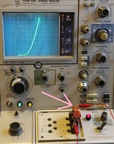
Read my report about the Tektronix 576 curve tracer, go to the part about testing diode curves.
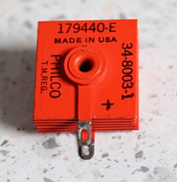
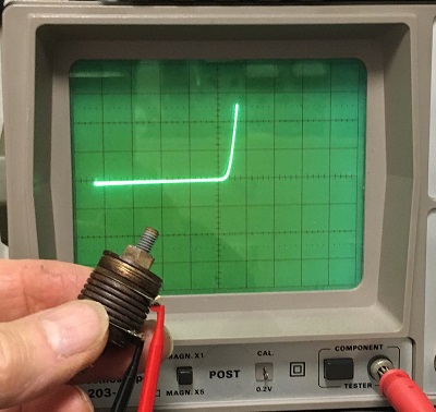
This 6-Cell diode of type 34-8003-1 Selenium diode was used for the above curve testing. The forward voltage can be seen, is 5V which makes sense as it has five plates, which normally have 1V each. So the reverse voltage is probably such that it can rectify the USA mains voltage of 117AC. I have not tested the breakdown voltage, but I think you can just normally rectify 117V AC with this diode. Given the forward voltage is only 5V, it should be able to to 50mA-
Each plate by itself is a diode. The anode is the one side, the cathode the other, and the junction layer is in between. So with help of metal rings, they could be very easily stacked, and in the center is just a rivet, or a long screw to keep it all together. Even single Selenium rectifiers plates were sold, where the user could stack them, to get the required break down voltage. On Ebay you can still find even High Voltage diodes, stacked of thousands of paper- thin plates. Doing several kV. You hardly recognise those as such, since is each plate is only a tiny ring, and they're all stacked on some isolating bar, appearing like a power resistor. These diodes had very good reliability, because if one of 5000 (!) shorts, the other 4999 still work.
Interesting Replacement instructions by Tektronix
References:
- Jackson, Selection and Application of Metallic Rectifiers, 1957
- Mierde & Kroczek, Selengleichrichter, 1959
- RFT, Selen Gleichrichter