How to choose Symmetrical to unsymmetrical transformers.
 |
The number one Question.... Can you send me a sketch, how to.... |
 |
In the explanations below, we identify a major cause of hum problems. Basically these are the two solutions:
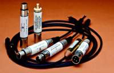 1) Use of "interconnect solution" cables from Lundahl, which have 1:1 transformers build inside.
 2) Attach the tone transformer inside the equipment.
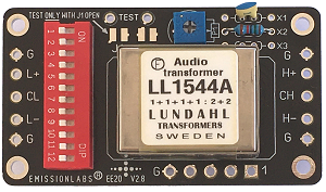
This is the EE20 board, which can do very much. There is also the less complex EE21 and EE23, or the universal EE08 board.
Any metal housing with working electronics inside, connected to the mains, will always have some small AC voltage on this housing. Reasons are many. First, the safety ground of your house is no "Zero" Volt connection. There is always some small, but very low impedance AC (hum) signal on it. This is coming from capacitive coupling of the "hot" AC wire, throughout the whole house. With hundreds of meters of cabling inside the walls, this capacitance is large enough to cause AC voltage on the safety ground. Now, the safety ground wire system in your house is connected to a "zero" volt connection, your electricity company supplies, and connected to the water pipes of your house, and to an additional earth grounded pin in the basement. So through "some" path in "some" way, "some" current will flow, and this is sure not very little current. The second mechanism is leakage current of all machines, and lamps and equipment that you have. These all have capacitice current to ground, via the mains transformers, and anything else which is grounded.
In the end, what we have here is a "zero" volt reference which can only be called such, for safety purposes. However, for signal purposes, this is sure no zero volt reference at all.Sill there is no other option as to connect the metal housing of equipment to this, because safety goes first. Now comes the problem: When connecting two pieces of equipment, there are always two things you connect: Now comes a problem: When connecting two pieces of equipment, there are always two things you connect:- Electrical signal
- The ground connection (metal housings, or shielding)
For tone transformers we have these requirements:
- Keep the bandwidth
- Enough voltage capability
- Give little loss.
If one the above parameters os over specified, this will go on the cost of the others. What follows now are some of the design considerations, and a list of recommended transformers.
Some design considerations:
Voltage capability. Don't over dimension this one. By Ohms' law we always have the situation that a "high voltage" signal is by definition a high impedance signal. That means if you choose the voltage capability of the transformer too high, you will introduce elements of a high impedance transformer. A higher voltage capability can be achieved with the same iron core, by using less copper and thicker isolation. If you overshoot in one direction, there is a problem at another.
Configuration. You can parallel or serialize the windings of a transformer, for getting best results for YOUR application. Also here, don't overdo it. Generally, parallel the windings will give a lower output impedance, and lower voltage which may be what you need. But... It will also give you more windings capacitance, which is bad. So paralleling windings can be done as long as you see not bandwidth problems arising. For output transformers this is more critical than for input transformers.
Copper Resistance. You will find this value in the datasheet. Copper resistance is something unwanted, but unavoidable too. Transformer copper resistance should be compared to input impedance. If the input impedance is 5k, 100 ohm copper resistance is not a problem. But if input impedance is 50 ohm (which is not very common), 100 ohm copper resistance will cause a signal loss of 2/3.
Transformer impedance. Transformers don't have an impedance of itself, but they transfer the impedance of the signal. So if you have an ideal 1:1 transformer and you transfer a signal of 3 Volt, with an impedance of 2000 ohms, what comes out is..... a signal of 3 Volt, with an impedance of 2000 ohms. The impedance of the signal is transferred with the square of the windings ratio. Transformers have a range of impedance which they can transfer. If you are confused with this item, it's best to approach the transformer as a voltage (signal) transformer.
Also, transformer impedance (no load impedance) should be reasonably high compared to source impedance. If source impedance is very high (which is the case for some tube pre amps), you cannot put a too low impedance transformer after it.
Step up the signal. This can be done, but needs good consideration. It should only be done when the source impedance is very low. The transformer transforms the load impedance with the square of the transfer ratio. This applies for the load of the transformer, and also for it's own windings capacitance. Here is a numeric example:
1:4 Step up
Suppose you step up a pre-amplifier signal with a factor of 1:4 (generally not recommended) here is what you get:
What do you see when you look into this transformer, from the input side? |
Transformer 1:4 |
What is this transformer loaded with? |
some pre amps |
Signal step up 1:4 |
47k Ohms For instance the input of an amplifier |
1:2 Step up
Suppose you step up a pre-amplifier signal with a factor of 1:2 (generally no problem) here is what you get:
What do you see when you look into this transformer, from the input side? |
Transformer 1:2 |
What is this transformer loaded with? |
most pre amps |
Signal step up 1:2 resulting in: Impedance step down 1:4 |
47k Ohms. For instance the input of an amplifier |
1:1 Isolation only
Suppose you isolate a pre-amplifier signal with a transformer (so no step up or step down) here is what you get:
(see also the next table)
What do you see when you look into this transformer, from the input side? |
Transformer 1:1 |
What is this transformer loaded with? |
|
Signal step up 1:1 |
47k Ohms. For instance the input of an amplifier |
1:1 Signal Isolation by transformer type. With conversion from symmetrical to asymmetrical
Line |
Type |
Use Board | Core |
Description |
Best for |
Bandwidth |
Maximum Signal level |
0.1 % Distortion |
1 |
LL1527 | EE08 | Mu-Metal | Classic product, widely used by many customers, for HiFi and professional applications. | Price/Performance | 10Hz --150kHz | +16dBU | 6dBU |
2 |
LL1527-XL | EE08 | Mu-Metal | High Signal Version of LL1527 | Price/Performance @ high signal | 10Hz --150kHz | +19dBU | 9dBU |
3 |
EE08 | Mu-Metal | Extremely high bandwidth | Bandwidth |
10Hz --200kHz | +16dBU | 6dBU | |
4 |
LL1570-XL | EE08 | Mu-Metal | High Signal Version of LL1570 | Bandwidth @high signal | 10Hz --200kHz | +19dBU | 9dBU |
5 |
Mu-Metal |
Low copper resistance, finest and ultimate 1:1 transformer. | Shielding and low R-Cu | 10Hz --100kHz | +28dBU | 10dBU | ||
6 |
LL1544A | EE20 | Amorph |
Very versatile, with many recommended configurations in the datasheet. | Users who prefer amorph cores. | 10Hz --70kHz Maximum 220kHz with tuning |
can be wired for 14 dbU(normal) or 20dBU (very high signal) |
3dBU |
7 |
LL1545 | EE20 | mu-metal |
Very versatile, with many recommended configurations in the datasheet. | 10Hz --70kHz Maximum 220kHz with tuning |
can be wired for 14 dbU(normal) or 20dBU (very high signal) |
3dBU |
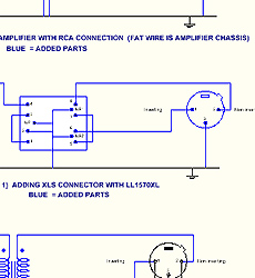
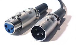
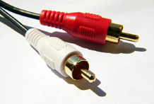
How to add an XLR Connector to an RCA Chassis / or RCA Connector to XLR Chassis
Click for schematics here
Note1: The Lundahl transformers have a special winding technology. The user will NOT be presented ONE input coil and ONE output coil, as with several low-tech products available on the market. The true construction is, the primary and secondary coils consist of more layers, sectioned into each other, and of most layers separate connections are given. Connecting this is less complex as you think and in each Lundahl datasheet. there is an overview of ready-to-build possibilities. This method results in best bandwidth and best waveform reproduction by the transformer.