Since 1993 Copyright Notice
Tube Amplifier Kits
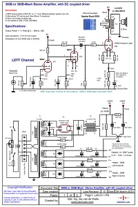
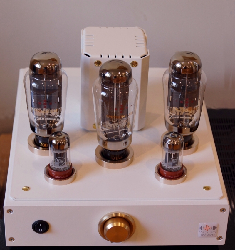
300B or 300B-mesh Classical Amplifier full description. Revision H.
When ordering materials for kits, you get 10% discount. This can be when you order it all together, or when you order some parts later too. This is not done automatically, so please ask for it when ordering and it will be processed with 10% discount.
Please understand, for legal reasons we must say, we do not guarantee the schematic. However, it has been build by several users, performance with the Lundahl SE and Mains transformer is very good. If there a problem when building it, please contact me by email, and I am sure we can solve this, as functioning of the schematic is very logical.
This beautiful housing was made by Anastas Kilda from Lithuania.
Please read some more feedback here.
Sound and electrical circuitThe pre-amp and driver circuit of this amplifier has been around since a long time, and can be found in similar circuits. DC coupled circuits always had their own charm, but they can behave unpredictable in the warming up phase, if two different tube types are used. If not designed well, a tube can pull excessive current, when it warms up faster than the other. To make this work safe, both tubes should be identical, which we achieve most effectively, when they are the same type, the same brand and the same age. In other words: A dual Triode in one bulb. The 300B output stage is a school book, classic auto bias circuit. As you may know, best sound, highest output power and long life, do not go together well, and most specially with Directly Heated tubes this is so. Amplifiers 'on steroids', proudly designed for maximum output power, don't have the softness of a single ended triode. Besides these wear our the tubes faster, it should come as no surprize. It is this disappointment which makes people use 2A3 tubes, or even Type 45 tubes in the end. However, when a 300B is biased just moderately, a less dominant sound of this tube will develop the same was as with 2A3 or 45. So the idea is here to get a nice and sweet sound in the first place. The result is an honest 7.1 Watt RMS , at the output of the transformer. This will need speakers with 91dB or better. It is not easy to describe or predict sound in words, but this bit we can say. The driver stage is set up as a low noise schematic, and the heaters are all with DC for this reason. When you build it nicely, this amplifier has no audible noise or hum. The SE transformers by Lundahl are amongst the best on the market, and it is possible to get this amplifier fully flat in the audio range from 20Hz to 20kHz. The 6SN7, initially I expected for such a DC coupled circuit, we would need carefully balanced tubes, but experiments showed this circuit works well on every tube at all. Even with a worn out 6SN7, testing in the "?" range, the circuit kept on working normal. In the 1920's a similar circuit was patented as the Loftin White. Low Hum is achieved by DC heating of all tubes. Also good and correct wiring is needed to get the hum at or below 1mV, but this is possible with normal effort. See the additional notes at the power supply for this. |
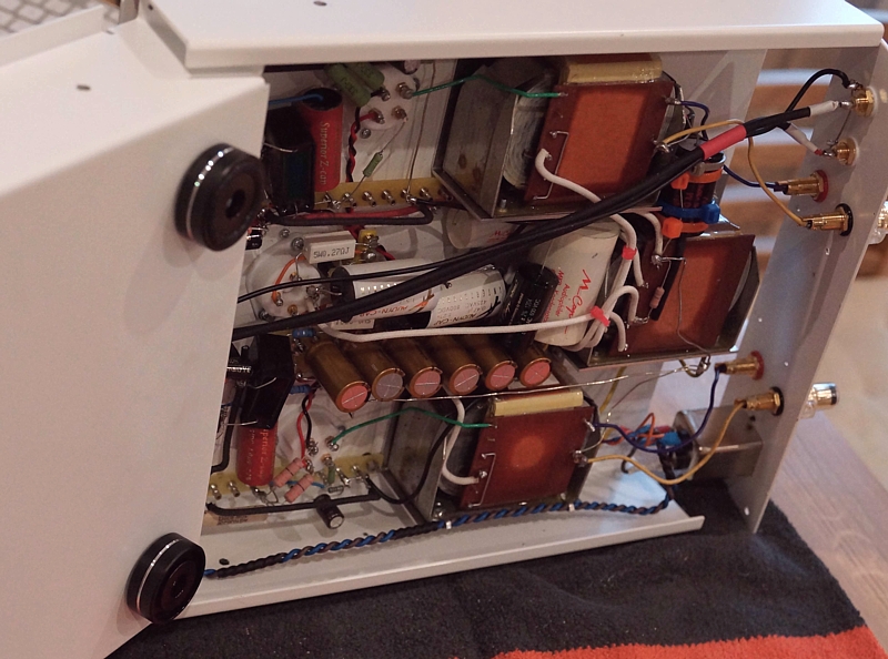
The power SupplyWe used a Lundahl transformer, which is in it's base construction the same as a tone transformer, so it is not a low budget mains transformer. Advantages are extremely low hum, virtually no stray radiation, and very low heat loss in the transformer. Even so, Lundahl mains transformers have the special capability to reject a small DC component as sometimes present on the mains today with all the modern heavy electronics connected. Low cost mains transformers can be found for half the price of a Lundahl, but that would be saving money at the wrong end. 115V or 230V. I have shown a nice way how the transformer can be wired quickly for 115V or 230V by adding one or two bridges on a five pole solder strip, but of course you can hard wire it directly to the right mains voltage as well. Calibration of the amplifier, to the Mains voltage. This is always needed with any tube amplifier, just not everybody does so. The mains easily can be 5% up or down, or even more. By itself not a major problem, but tube heaters must be within 5%. In case of some doubt, it is better to over heat the tubes with a few(single) percent, than under heat. Best is however, do it correct. That will give best tube life, and it makes really a difference. That is why we use those series resistors in the tube heaters. The method is simply, first measure how far the mains is off. Suppose the mains voltage is 5% too high at the moment of calibration, in that case, the series resistors are adjusted such that the heaters are also 5% too high also. (So not compensate the mains error). Then, at some other day, the means is 3% too low perhaps, and the heaters will also be 3% too low also. As an average the tubes will be at 100%. |
About some of the parts usedResistors we don't sell. Capacitors we sell only when there is an order number for it, in the parts list (all below here). Though not on the parts list, consider the transformer caps from Lundahl, these are from magnetic shielding steel, and also these caps can be opened while mounted, and you can work or measure on the wiring. They're really convenient, and very good looking transformer caps, powder painted so they won't scratch, and a gray on black Lundahl logo on it. A potentiometer is used at the input of this amplifier. Of course it can be removed, when you don't want to use it. In that case it is recommended to change the grid resistors on pin #4 of the 6SN7#s to 10k. However, many pre amps today produce far to much signal, so it may be a good idea to have a volume control on this 300B amplifier. Like this you can adapt the amplifier's sensitivity for maximum output signal at '100%' volume at the pre amplifier. Why to do so? First, this will give more convenient volume control at the pre-amp. Also, this will reduce the overall noise of the system, when the preamplifier is of a somewhat noisy type, which is more or less always so with tube pre amplifiers. If the pre amplifier is allowed to play at higher signal level, the noise stays the same. So signal to noise ratio gets better. The higher output signal is then attenuated with the input potentiometers of the 300B amplifier, while still using the pre-amps volume control as such. This method of noise reduction really works, and cost only a potentiometer.
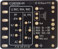
We recommend the use of PCB EE63 together with transformer LL1663. If using not solder wires, this fits nicely inside the LUNDAHL transformer covers too.
|
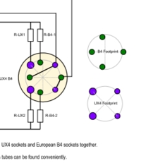
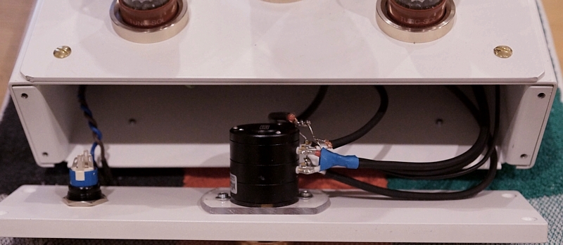
The rectifier tubeWe used the 5U4G mesh by Emission Labs. It is very interesting to replace rectifiers by different types! Theoretically this makes no difference, but from blind hearing tests I once did with theLuxembourg Audio Note distributer, I changed my opinion. The Yamamoto Dual rectifier tube socket. The schematic we use here, generates the heater voltage here, with the series resistors in the rectifier tube heater. This allows a variety of rectifiers can be used by adapting the series resistors. Tubes can be used such as RGN2504, RG2004, AZ4, or AZ50. If you decide to go this way, note the supply winding of 6.6V unloaded, and has 0,1Ohms internal resistance, so you can make your calculations. Please check this drawing for how to use RGN2504 or RGN2004. We have stopped selling Yamamoto products, these sockets we has as long as stock lasts. |
Some design notes, unsortedAmplifier schematic.This DC coupled schematic is around for a long time, you can call it a classic schematic. |
Bias of the 300BThis is chosen relatively low at only 22 Watt. Yet this is a remarkable good working point, and a beautiful sounding 7 Watt will result from this. This lower power will take away the 'dominant' sound any 300B will have at higher dissipation, so sound at 22 Watt dissipation becomes a bit sweeter, more triode like. |
Option to use EML 300B-MeshAnother advantage is the possibility to use EML 300B-Mesh here. At 22 Watt this is the perfect working point for this tube. The higher transparency of (real) mesh tubes will amaze you, provided you have high quality speakers which can reproduce this. |
Grid stopper of 300B tubeTo the grid of the 300B, you will see a series resistor of 470 Ohms. The function if this resistor is to block RF signal going into the 300B. Historically this worked well to prevent AM Radio transmitters to inject 'voices' into the tube. Today, it blocks any RF signals from mobile phones. The value is uncritical, but I prefer to keep the resistor low, because a 300B tube can pick up hum signal via the grid. This hum gets shorted by the output of the driving 6SN7, but then we should not connect it with a very large resistor. |
The pre amp and driver using the 6SN7 tube.6SN7 at it's time was the most produced dual triode, which happened unintended. Originally, it was designed to have a tube like: 'What goes in, is what comes out". Then, when Television was introduced, 6SN7 became the standard tube for the vertical oscillator of the picture tube. So it became produced in large quantities. From those days resulted the GTA and GTB versions, which were essentially the same as the standard GT, but with faster warm up time. This helped starting up the TV faster, because as long as the tube was not fully warm, the oscillator would not be stabile, and the picture would roll. In our circuit, we have one 6SN7 driving another. This needs some consideration, because the driving 6SN7 has a reasonably low output impedance, but it's 7k7 is not extremely low. This has to drive the next 6SN7. This tube has not neglectable grid capacitance, because Grid to Cathode distance is quite small. Effectively the capacitance is 20x higher, because the tube gain is 20x, and we call this the Miller effect. This capacitance will give some roll off in the15kHz range already. In some circuits you can see the driving 6SN7 consists of two tubes in parallel, which works well, because that reduces the output impedance a factor two. It costs however an extra tube. To prevent this, we use a method called compensation. The 15nF capacitor, as you see with the bias resistor, has no use for lower frequencies. This means, in the low range there is some feedback, via the cathode resistor. (Because the 15nF has no effect). This is also good, because otherwise, the overall gain of the amplifier would be too high. This small feedback reduces now the gain of the first tube, and also reduces it's distortion, and it's noise as well. Then at appr 15kHz, a small roll off begins, and this is exactly where the 15nF Capacitor comes in, and begins to short the bias resistor. This will make the gain of the first tube go up, and at the output signal is now linear. As a side effect, a frequency roll off will always come with a phase error too, which error is now also not taking place. This corrects also the phase error, which would otherwise have resulted from the roll off. So no, the 15nF capacitor is not too small, as you may think initially. In the 1920's, a similar circuit was patented as the Loftin White. As a side effect of not decoupling the bias resistor of the input tube, it became necessary to heat the tube with DC voltage, because with AC, it would pick up hum otherwise via the none-decoupled cathode resistor. |
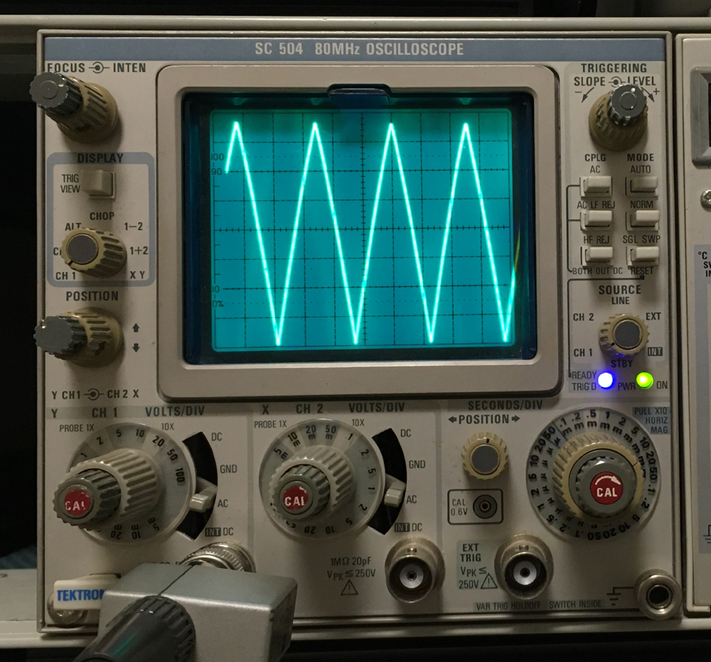 This is about the maximum the driver stage can do, before distortion comes in. Pictured here with 1kHz Triangle. (Triangle shows quickly if signal peaks are distorted ). This 1kHz signal is at 160 Volt peak to peak, which signal level is as much as the circuit can do safely. Above 180Vpp, it begins to distort. Tube was a 1960's 6SN7 (6H8) NOS tube, from Russia. The undistorted peaks at the bottom are only possible with a lot of emission of the tube. So it will saturate well. This is about the maximum the driver stage can do, before distortion comes in. Pictured here with 1kHz Triangle. (Triangle shows quickly if signal peaks are distorted ). This 1kHz signal is at 160 Volt peak to peak, which signal level is as much as the circuit can do safely. Above 180Vpp, it begins to distort. Tube was a 1960's 6SN7 (6H8) NOS tube, from Russia. The undistorted peaks at the bottom are only possible with a lot of emission of the tube. So it will saturate well. |
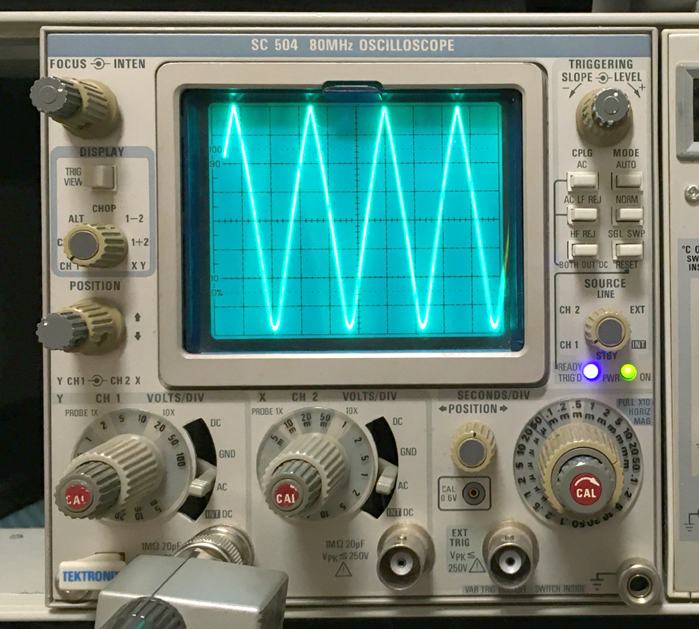 The same set up, nothing changed to the circuit or the scope settings. I only replaced the 6SN7 by a worn out tube from the 1950s. That (bad) tube tests only at 55% at a Hickok tester, and it is also totally unbalanced, this tube is junk, I just have it in my "bad tubes" box. But now look, how reasonable this circuit still works on it. Note the rounded edges of the triangle wave at the bottom, So yes, it does something "negative" to the circuit, but this tube is totally JUNK, and still this circuit works almost good in it. So I think we can say, this circuit works on any good tube. The picture quality is lower, but that is just caused by my Iphone camera. What you need to look at, is the measurement. The same set up, nothing changed to the circuit or the scope settings. I only replaced the 6SN7 by a worn out tube from the 1950s. That (bad) tube tests only at 55% at a Hickok tester, and it is also totally unbalanced, this tube is junk, I just have it in my "bad tubes" box. But now look, how reasonable this circuit still works on it. Note the rounded edges of the triangle wave at the bottom, So yes, it does something "negative" to the circuit, but this tube is totally JUNK, and still this circuit works almost good in it. So I think we can say, this circuit works on any good tube. The picture quality is lower, but that is just caused by my Iphone camera. What you need to look at, is the measurement. |
6SN7 matching or balancingWhat is interesting, initially I would have expected for such a DC coupled circuit, carefully matched tubes would be needed. My experiments showed, this was absolutely not necessary. This circuit worked even well, using worn out 6SN7 tubes from my junk box, which where at 60% Emission only. I have seen other DC coupled circuits, where indirectly heated tubes are DC couples with directly heated tubes, but these are unpredictable. The directly heated tube always begins to work after a few seconds already, while the indirectly heated tube may need half a minute before current begins to flow. During that short time, the circuit works in an undefined way, possibly causing tube damage. In our circuit here, we don't have this issue, because both 6SN7's in one bulb are heating up the same way. |
Good functioning and power supply considerations:You need to look at the values of the parts, which are responsible for the final voltage. These are:
Alternatively, use the newer Mundorf Tube Caps. These are bipolar electrolytics of a new technology, these behave like foil caps. They are only 2x larger than electrolytics, so much smaller than foil caps. They have amazing low internal resistance. So to say they combine the virtues of Electrolytics and foil caps This technology was introduced silently, but indeed this is new kind of capacitor, intended for power supplies. They do have a few uA leakage, which is irrelevant for a power supply, but they can not be used as coupling caps. They are available in very few values only, so these are good when you need basically just a high value. |
Power Supply Schematic.
The Historical 'Kaneda' Circuit. The typical Lundahl 'CMR' topology for the choke is not new. The nice part if this is, it seems to isolate the rectifier part from the capacitor part better, because there is also a choke in the ground circuit. Yet, this can be wound on one core, and we loose no inductance, as long as the DC path of each choke is chosen correct. (Just use our schematic, and connect pins 1,3,4,6 of the choke this way). Note, this circuit is almost like choke loaded, as the first capacitors we choose very small. The Kaneda circuit does this as well, though you may see 'large' capacitors, but the Kaneda is a low voltage circuit. Yet, the idea can of course easily be adapted for high voltage too. For the choke used (T4) we definitely recommend a Lundhal, or any other type that can be used choke loaded. Being able to use it like that, is a quality element of any choke, and such chokes give no audible mechanical hum, also not after longer time. Low cost chokes will work initially, but choke loaded means higher mechanical (resonance) force on the windings, and if they becomes loosened over time, some mechanical noise will appear. This is no real defect, but it is annoying. Note, the choke is connected here in so called CMR configuration. You will find more information about this in the Lundahl Tech corner, here is a direct link, go here but remember to choose this chapter '1.1 Chokes for PS'. These are similar to the Kaneda circuit, but technically improved by Lundahl, and adapted for use with tubes. Take a closer look at this CMR circuit, and you will see there is no direct connection anymore from any part of the transformer or rectifier circuit to the power supply output, other than going via the choke. Knowing a choke cannot pass AC signal, this becomes a near-perfect l method to prevent power supply ground loops. It is of course only possible with dual chokes such as the Lundahl. A miracle, nobody ever patented this! For the tube rectifier an electrical symmetry point is created with two silicon diodes. I quote Per Lundahl's words here, that such a center tap will prevent mechanical hum, since it will per definition divide the transformer flux over two windings, at the moment the mains makes one half cycle. So it means if there is the positive cycle, the current flows still through both transformer halves still. Same for the negative cycle, but in the other direction of course. Still each cycle passes the rectifier tube the normal way. This will give a dead-silent operation of the main transformer. Try out the current path, and you will see! |
PARTS LIST! Note = 1 x 300B-300B-MESH Amplifier Parts List |