Electron Engine ™
EE61 Universal Experimenter PCB for Triode.

Introduction
EE61 is a universal board to evaluate a Directly Heated SE amplifier circuit. It features several status LEDs, and many ways to connect instruments conveniently.
The filament can be heated classic, using AC or DC, or be heated with one end grounded, using DC heater modules. To try out the different effect, you can quickly change between those heater modes with solder jumpers.
Bias method can be changed between Auto Bias, Mixed bias, and Adjustable Bias. For mixed and adjustable bias, the plate current can be changed by applying a negative voltage to the NGV input.
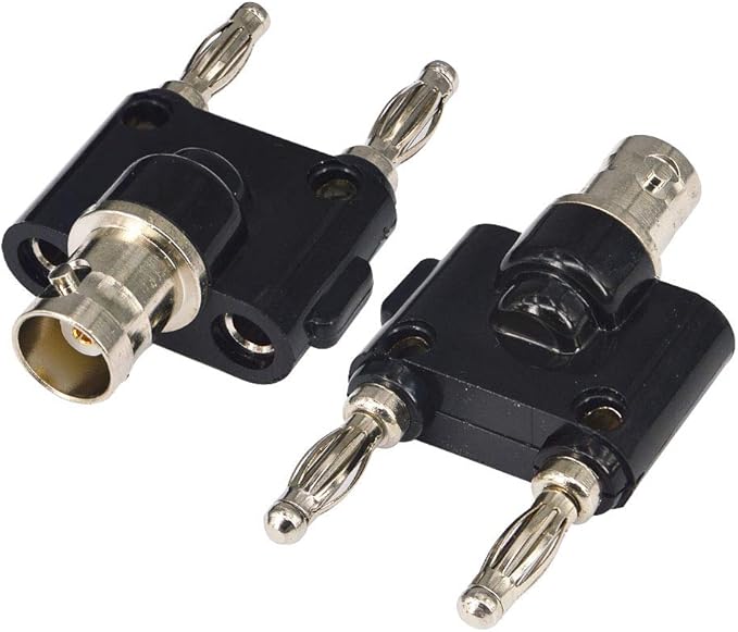
Cables can be connected with banana plugs or screw terminals, or just soldered into the PCB holes. Signal input and output terminals have also the correct distance to fit a banana to BNC adapter, so an oscillator or oscilloscope can be connected conveniently.
Description
Though the schematic seems a bit complex perhaps at first sight, this is not so. Once set for a specific circuit, it becomes reduced to function of this circuit only, for which below here three examples are given: Auto Bias, Adjustable Bias, and Mixed Bias.
In Addition the board can be used for tube burn in, or verify some working points of the tube curves, when the SE transformer connections are shorted.
When using balanced filament heating, (so not one end grounded) the output current can be made visible on an oscilloscope, or use a multimeter instead, and measure DC current and AC signal. For this, a current sense resistor is on the board.
The board EE61 can be operated together with the universal power supply board EE40, or be used with any other power supply of yourself.
DIMENSIONS of 100 x145 mm, may seem large, but there are many connectors and wires attached, and tubes like 300B are not small items too. Initially the board was much smaller, but that made it inconvenient to use.

This is the full circuit, but not all functions are used at the same time.
Features
- Orange Filament LED will burn on AC or DC. If DC, it also indicates correct polarity.
- Blue Hazard LED on High Voltage is recommended for your safety.
- Gas Test. EE61 has provisions for this. Read the notes for more information.
- Output fuse, to work without transformer initially, at first set up.
The following works only with Auto Bias and Mixed Bias
- Green LED indicates Plate current, just analog.
- Red LED has a threshold value. It burns only when Plate current exceeds it's normal value.
- Settings of the red and green LEDs works automatic, because it's derived from the Bias voltage. How to do this, is printed on the EE61 board.
- DC Current and AC Signal monitoring at the Rm Output.
Board Order Number: 311-061-69
About SAFETY
Anode Current. The Anode current is indicated by the green 'Normal' LED, and it burns at any current. The red 'Fault' LED, burns only, if a user defined, current is exceeded. Even so, you could connect an opto coupler instead of the fault LED, and create your own shut down circuit with the opto coupler. In addition both DC and AC signal can be measured via the Rm output, using a normal multi meter, or an oscilloscope.
The Rm Output. This an analog output, to check anode current. A Voltmeter can be attached with banana plugs. Just set the voltmeter for DC to measure plate current, or set it to AC to measure signal. Or, an oscilloscope can be connected to Rm, using a banana to BNC adapter.
Beware. When interrupting DC current of an unloaded SE transformer, this may cause a windings damage when there is no secondary load. This is why a tube amplifier should never be operated without a speaker connected to it. On the bench this could happen when you disconnect the high voltage supply by mistake. So best is to use banana plugs or soldered wires.
First switch on. This is where you have your SE transformer at risk. Before using an unproven circuit for the first time, it is advised to unplug the transformer, and plug in a fuse instead. Like this, the fuse replaces the transformer. Bias of the tube, can now still be tested, via the Rm Output. How this is done, is explained in the notes. If the tube appears to work as it should, it can be tested with the transformer inserted.
BIAS Schemes |
1. Auto BiasThe classic scheme ever since, with good reason. Little can go wrong with this, and output power is the highest. |
2. Variable Bias with DC heater modules and grounded filament.This is a bit "trendy" but I really have to say, this is not a very good circuit. This is only used because people who sell regulated voltage or current regulated PCB's present this too simple. You are heating the tube unbalanced, with all disadvantages resulting from an unbalanced circuit. One disadvantage is, the much higher hum susceptibility of the tube. So this can ONLY work with an extremely well stabilized heater. But what a coincidence.... that's what these so-well-designed circuits are capable of. Just what you need, right? . And it is hum free, it really is. Well yes, but it stays an unbalanced circuit. This is not to write against such modules, because you can as well use them with mixed bias auto bias, or auto bias. Another issue with a grounded filament is the following. For safe design, you need to bias already with an Auto Bias circuit, approximately 10% below the absolute maximum. Such as 300B in Auto Bias, though a 40 Watt tube, safe design ends at 36 Watt. WIth adjustable bias you need to go another 10% below that. Many historic tube tube sheets say so, and it is with good reason. So with adjustable bias, tubes should not be biased higher than 80%. This has nothing to do with the EE61 board, but safe design in general. What stays however, the tube is used unbalanced, and hum susceptibility will be higher by definition. If the above is no problem for you, here is how to use EE61 with a grounded heater:
Filament and Vb+ LED functions are not shown, but they are used.
|
3. Mixed Bias with DC heater modules, or AC heaterThis is the best circuit. You can adjust the amplifier, but it still runs in Auto Bias mode. Not fully, but enough to stabilize it. The filament is heated "balanced" and such circuits are much less hum sensitive. This means, the tube can AC heated, if used as speaker output tube. Or, if heated with unstabilized DC it becomes already hum free. To adjust the DC current, all it needs, is a small voltage to the 'VAR' input. If you unplug the voltage, the circuit falls back to normal auto bias. This allows to use any normal auto bias circuit, and decide later to change the current, without having to change the cathode bias resistor. The change is equal to the tube transconductance. For instance, the 300B tube has 5mA/V. This means for every volt on the 'VAR' input, the Auto Bias set point changes 5mA. Interesting, the current can be changed up and down, by reversing the voltage. So to repeat it, the mixed bias circuit requires no changes to the Auto Bias circuit. All it needs, is a DC control voltage to the 'VAR' input, and Mixed Bias becomes active. An interesting way to use Mixed bias is to build a soft start circuit around it. This is not part of the EE61 any more, but it can be added easily. For this, the auto bias circuit initially is designed for 70% of the normal current. The other 30% comes from a positive voltage on the 'VAR' input. Initially the circuit starts slower, and also does not go further than 70%. Now, positive voltage is present on Rk. From this voltage, with a voltage divider the required 'VAR' voltage can be derived. So additional components is just two resistors. The capacitors of the 'VAR' input will delay this action, and circuit start is softer than normal. A real slow start from zero can also be made with a negative voltage on the 'VAR' input. This requires more circuitry, which is only for advanced designers. The method is, to use normal 100% bias, but cut off the circuit down to 10% at switch on, with a negative voltage on the 'VAR' input. Once the tube begins to work at 10% on this condition, first takes a while. Then, this is detected by a voltage across the cathode resistor. Now, a circuit triggers on this. The negative voltage is removed from the 'VAR' input, and it will go to zero. By adding larger capacitors across the 'VAR' input, like 200uF this action will be slowed down. By itself, this method is safe, since at any failure or design mistake, the tube will not be able to bias higher than 100% anyway. Yet any slow start experiments should be done all in the end, when you find the circuit works well without it.
LED functions are not shown, but they all four LEDs are used.
|
4. Tube Burn in.Is has to be said, burn in is capable if repairing several problems or even defects. For this it has to be done the right way. This includes using the appropriate Bias Scheme: Mixed Bias, and then basically perform the procedure. This can be general, or specific with respect to a certain problem, knowing what this is, and what to do. On the other hand, not everything can can be cured by burn in, and the use hours a tube has already seen, can't be retrieved. Still there are things we can do. |


