Electron Engine ™
Printed Circuit Boards by Emissionlabs
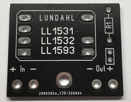
EE31 Gold Plated Printed Circuit Board, for L1531, LL1532, LL1593
- Gold Plated PCB
- Easy to use, RCA or XLR.
- Breaks the ground loop
- Requires very little space
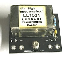
- High Impedance with LL1531
- 600 Ohms with LL1532
- Audio grade 'Green Drop' Capacitor included
Order Nr: 310-031-27.
Included:
- PCB EE31
- Audio grade 1.2 nF 'Green Drop' foil capacitor. Used for L1531, LL1532, LL1593.
- Screw and distance holder
Not included: LL1532 and LL1593 use a 2k7 resistor. For LL1531 use an 8k2 resistor.
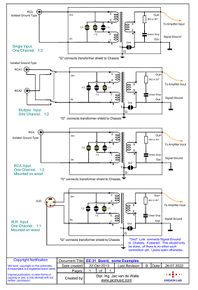
Some applications
In tube amplifiers, we recommend this PCB with LL1531, to break the ground loop. It is not necessary for this to change to XLR connectors, it can also be done with an RCA connector, as long as the RCA connector is an "isolated ground" type. These are the ones with separate connections for ground and signal, and the ground connection must be connected to the EE31 board instead of to the chassis. (It is the second option, below here)
In tone studios, using LL1532 supplies 600 Ohms impedance, a very space saving solution.
Transformers used:
- 47k Input with LL1531 transformer
- 600 Ohms Input or Output with LL1532
- LL1593 (unshielded version) is not recommended.
Function of the 'Gnd' link
EE31 can provide an isolated input, or an isolated output. In each case, the Gnd Link has another function.
- Most of the time EE31 will be used as input board with LL1531. The Gnd Link is then closed. This grounds the "Out-Minus" Terminal, and the "Out-Plus" Terminal provides the output signal.
- If used as an output board, the intention is normally to convert an existing unbalanced RCA output to an XLR Output or to a balanced RCA output (isolated ground type). For this, the low impedance transformer LL1532 has to be used. In this case, the Gnd Link is left open, to obtain a floating output.
Connection details is in the following text.
1)Add an XLR input
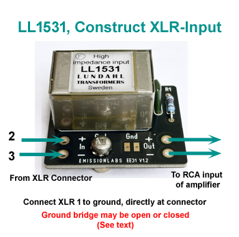
- Replace the RCA connector by an XLR connector.
- Or, mount the XLR connector in parallel to the existing RCA connector, as described here.
- Make sure the mounting screw is grounded. (Measure this)
- Mildly twist the wire pair connected to XLR2 and XLR3. Do not twist it with ground.
- Experiment with 1:1 or 1:2, what you like most. 1:2 gives more gain, but if this gain is not needed, 1:1 is probably better.
2) Balanced RCA input for unbalanced amplifier
This can be done, to have the same effect as XLR inputs, but you want to use the existing RCA connectors.
Click here for more info about this
3 Convert RCA Output to XLR Output
This is an OUTPUT application. Using LL1532

- Connect RCA signal to In+ and In-
- XLR 2 is connected to Out+, XLR3 is connected to Out-, XLR1 is grounded at the XLR connector..
- Ground link is left open
- Use 1:1 connection.
4) DUAL RCA and XLR input
Purpose:The amplifier already has a standard RCA input, which is mounted nicely, and it can be used together with the (new attached) XLR input. After this, also the RCA input will be balanced.
- In case the RCA connector was a 'grounded type", so the outside ring is grounded to the chassis, remove this connector. It must be replaced by a 'floating ground" type.
- Sometimes a floating ground RCA connector was already used, but the outside ring was grounded with a small piece of wire. This makes it easier. Just disconnect everything from this connector. Check with an ohms meter, if the outside ring is indeed floating. If yes, this is what we need. If no, you need to replace the connector with a floating ground connector.
- Check in the drawing here how the connectors are attached.
Position of the board inside the amplifier
Since the input of the EE31 board is symmetric (also called balanced), placement inside the amplifier, length and path of the wiring becomes uncritical. This is the first advantage of balanced inputs. Yet it is good practice still, to mount any low signal devices not too close to mains transformers or chokes.
The EE31 board can be used with two gain factors, using the solder jumpers.
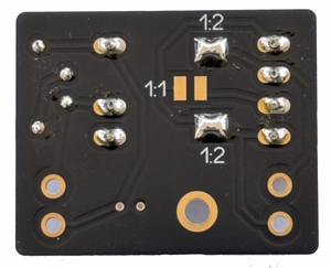
Pictured here is setting for 1:2
For existing d applications. 1:1 is advised.
For new designs, 1:2 is advised., This makes the following stage easier, or even the first tube can be eliminated. There is already gain with a factor two, directly at the input. Unlike with tube or transistors, this gain is achieved at the most sensitive point, noise free and hum free.
Background Information
 With RCA inputs, unless a transformer is used, we have an unbalanced (unsymmetrical) input. This works free of hum in many cases, just not in all cases. In case there is some residual hum, it has most of the time of of the two following causes. One cause is, the signal cables may form a ground loop, which picks up hum signal, radiated by mains transformers and power supply cables. Also called a ground loop. Another cause is capacitive AC current, simply from one equipment to another. Mains transformers always have some capacitance from input winding to output winding, it is unavoidable. With the mains voltage across this capacitor, by definition a small AC current flows, which leaves the equipment via the mains ground wire. So this capacitive current flows from the hot side of the mains, to the safety ground of the mains. Since safety ground by law, must be grounded to the chassis as well, a small AC voltage on the chassis results from this. Theoretically this would play no role, as long as the safety ground of your house as ZERO volts on it, if the ground wires of your mains cables have ZERO ohms, and mains plug resistance is ZERO ohms. All of this does not apply, and so this capacitive current is going to have some effect. The equipment with the higher capacitive current, will build up a small AC voltage on the chassis. This is very little, but it is there, because we have no ZERO ohms at the above places. Equipment with a lower capacitive current will build a smaller AC voltage on the chassis. These voltages are small, but they are present. Now comes an issue, when we connect the one chassis to the other with a grounded RCA cable. This capacitively generated voltage between the two chassis, is now shorted by the RCA shield wire. Since this can not be a zero ohms cable, some voltage may result. In other words: Hum. So this is when people try to reverse mains connectors, work with gold plated mains plugs, best quality RCA plugs, etc. But it is only "dealing" with the problem instead of removing it.
 WIth an XLR input, the situation becomes TOTALLY another. This bad situation, where signal wire is ground wire at the same time, is avoided with XLR, but it does cost another wire. Here, we have TWO high impedance inputs, and one ground wire. This ground wire, carries no sound signal, and the two signal wires carry no ground current. Problem solved! It is hum free by definition, and the standard in all professional equipment. Besides (don't tell the HiFi nuts...) contact quality of XLR cables is hardly important. So the cheapest XLR cable works better than the most expensive RCA cable.
An XLR input can be created electronically, these are two input lines which respond only to a differential signal. This can be done with tubes or transistors, but it increases costs very much. When the amplifier is already made, 99% have only RCA inputs, but we can create a real XLR input with an input transformer.
A third option would be to create a semi XLR input with a 'floating ground" RCA connector. This has all the virtues of XLR, and it means we need almost no change the looks of the amplifier, and there is no need to replace any RCA cables by XLR.
A fully universal amplifier can be made, by connecting an isolated ground RCA connector in parallel to the XLR.
About LL1531, LL1532, LL1593.
Despite their small size, LL1531 and LL1532 are offering very high noise suppression, due to the electrostatic shield between primary and secondary, and the use of a Mu-Metal housing. (Mu metal is the best shielding material, but it is quite expensive, so you find it only used with tone transformers).
LL1531 is a very small, but very high quality audio transformer. This is the normal High Impedance Input type for HiFi Audio, and the most sold version. Suited ideally for 10k...47k inputs. It gives 1:1 conversion for the signal, and does not change the original input impedance. So if the amplifier was 10k or 47k before, it will also be 10k or 47k after. It can do signal levels up to 10....20dbU, which is more then enough for any HiFi amplifier.
Use LL1531 1:1 or 1:2. The official Lundahl data sheet writes, LL1531 is recommended only as a 1:1 device. So officially we say the same. But...when driving LL1531 with a low impedance source, it worked very nice in 1:2 mode just as well, and no reduction of the frequency range at all. At least you could try it with this EE31 board, just set the Jumpers for 1:2. Generally though, the sensitivity of any pre-amp should be set as low as possible. When 1:1 works good, this is the best choice.
LL1532 is more a low impedance type, intended to be driven from a 600 Ohms source. This one can do officially 1:1 or 1:2
LL1593 is a low-cost version of the LL1532, with the same winding structure but without internal Faraday shield, and it has a lower grade metal housing. (no mu metal). This is for applications needing less noise suppression. We do not recommend it, but it is intended for high volume, very price sensitive applications, in a low-hum environment.
Some final hints:
Resonance tuning
 Use of the small RC network is recommended. Though it works also without, it gives excellent response to a 1kHz square wave signal, and it widens the frequency range, to a fully linear characteristic up to 25kHz for the high impedance transformer LL1531, and 50kHz for the medium impedance transformer LL1532.
For LL1531 use 8k2, and the green drop capacitor we supply.
For LL1532 use 2k7, and the green drop capacitor we supply.
1. Experimenting. If the EE31 board is not yet mounted to the amplifier chassis, provisionally connect a wire from the screw hole, to the chassis. Otherwise the transformer shield is unconnected, and the board will not function as well as it can.
2. Careful. Never use an Ohms meter to measure copper resistance of a winding. Such meters inject a 1mA test current into unknown devices. (Try to measure the resistance of an LED, with the anode to the red cable, and you will see it lights up nicely). 1mA would magnetize the core, and the transformer may distort afterwards. For testing audio transformers windings, attach a 10Meg resistor in series with the ohms meter. Then for a good winding, the meter indicates 10 Meg, and "open" if the winding is open.