Electron Engine ™
Printed Circuit Boards by Emissionlabs
EE21/23, EE23, Information about Tuning
- Overview
- MC Applications
 MC Tuning (you are here)
- All Connection Schemes, Complete Overview
- Unsorted Application Information
Understanding the calculations for tuning is nasty, and with EE21 it is not really needed. So this text is only for the interested reader, and for people who want to tune in detail and understand why things are the way they are.
To begin with, you can just skip the tuning when sounds good already as it is. This is the first possibility.
The idea of EE21 is to use a potentiometer for tuning, and simply find out by hearing tests what value sounds best. After you have found out the best setting, you can leave it as is. That is the second possibility.
Or, you can replace the potentiometer by a fixed resistor of the same value. To make this possible, the potentiometer can be electrically disconnected by opening solder bridge J8. Also, AFTER J8 is open, you can measure the value of the potentiometer at the test points, without having to remove it. That is the third possibility.
Why do amplifiers have 47k input impedance?
In 1935, the home equipment was typically a radio with a record player input. This input had an impedance of 47k for a specific reason. Most record players had a crystal cartridge, which worked quite reasonable actually, and they were manufactured until the 1970's. The advantage of a crystal cartridge is, when terminated with 47k, this achieves something like a RIAA curve. That was the only reason for this curious impedance, and it became the standard ever since. Even today, people get a strange feeling in their toes, when the input impedance of an AUX input is not exactly 47k, but 39k. Yet I advise to connect a resistor of 5k across it, when you have small hum, and with 5k it may well be gone. In professional environments nobody uses 47k. Why should they?! Nobody likes hum. They are using 600 Ohms, because that rejects hum much better, and any signal source which can not drive 600 Ohms, it is not a good source anyway. .
Yet for RIAA inputs, we talk about something else. Crystal record players are not used any more. Magnet cartridges, MM and MC, have long found their way into HiFi. Initially, MM cartridges were designed to work well at exactly 47k, because all radios had 47k already. That worked fine, and may stay like that.
A problem comes however with MC cartridges, because these are by nature low impedance. Like all low impedance devices they work at low voltage, high current. Now, with semiconductors this is already difficult to amplify free of hum and noise, but with tubes it becomes really very difficult. The MC transformer is our friend here. These give gain of of usually 3...32x, and of course without adding noise or hum. We do not get this amplification for free, because a step up transformer has a very low impedance at it's input side, but look.... the MC cartridges are low impedance too :) So the whole picture becomes perfect, because we are getting this low signal amplification at such an excellent level of low noise, this can never be achieved with any active amplifier.
One of the things to look at is the damping, this is explained in the next text part.
Damping of the cartridge needle
 Why is needle damping done? It ensures good contact between the groove and the needle. Also called tracking. This is beyond the scope here, but it is obvious that the groove will heavily shake the needle. This adds some random self movement to the needle. Even when not much, this self movement must be avoided, because at that moment, needle is not following the groove exactly. The solution against this is needle damping. This can be conveniently be done electrically, by just placing a resistor at the MC Transformer secondary side. When the system is damped, we lose a tiny bit of overall signal, but we lose most of all the self resonances.
The damping network of EE21 is universal. So the whole network as such is never used. Only some part of it is be selected, with J5 and J7, while the network can be connected or disconnected with J8.
So what damping or damping network do we need?
This is not easy to answer quickly! It depends on the cartridge. The manufacturer specifies a so caller minimum load, which is a value in Ohms which you may not go below. In other words, when the minimum load is 100 Ohms, you can load it with 150 Ohms, but not with 50 Ohms. If you do go below, you lose too much high frequencies, and also signal in general. Though it would be possible to damp the cartridge at the primary side, there is good reason to do so at the secondary side instead. If damped at the primary side, things automatically fall into place. Very low impedance cartridges give very low signal, but we can transform this signal up easily, just because it is a low impedance cartridge. If the cartridge is medium impedance, it will give a lot more signal by itself, but this signal can not drive a 32x step up transformer any more. Perhaps only a 16x transformer. So the output signal is more or less the same, and so is the output impedance. That is because the impedance is also transformed up by the transformer. So a very low impedance cartridge appears as a high impedance device at the secondary. Since all cartridges appear in a similar range at the secondary side, the standard damping resistor of 47k, by the phono amplifier input, will already give a very useful result. The rest is only fine tuning.
Here is a calculator to calculate the secondary load resistor. Note, this is for a RIAA amplifier with 47k impedance, and it does not take into account the DC Resistance of the coils. Though knowing the coil DC Resistance is theoretically needed, we can skip this with the EE21/23 board, because the damping resistor is variable anyway with a potentiometer, and we simply adjust for best sound.
So please use this calculator only for your understanding, but final tuning has to be done by hearing tests,
Note: If the damping resistor is negative, you entered a combination of minimum load and Step up factor, which is impossible. The same is, when the damping resistor becomes unrealistic. In that case, it would not be impossible, but the cartridge data you have entered,is unrealistic. You need to enter real, correct cartridge data, and you get a correct answer.
Now, after having calculated the value of the damping resistor, you want to know where to put it on the PCB. For this, you need to decide if you want a fixed value, or if you want to experiment with an adjustable value. Both is possible.
- For a fixed value, close J8 and J5 ,open J7, and put the fixed resistor at the position R1 of the PCB. That is all there is to do. In the circuit diagram, you can see the damping can be switched off by opening J8. That is to experiment with it, and hear the difference.
- For an adjustable value, close J8, open J5 and J7. We use R1 and P1. For P1 we choose 2x the calculated value. . Take the closest value which is commercially available. For R1, we use 20% of the calculated value. Using R1 prevents a short, when P1 is set close to zero ohms. Like this we can vary from 20% to 220% of the calculated value. Make sure, you put in potentiometer in the correct position. The center tap of the potentiometer is indicated at the PCB, with it's "variable resistor" symbol.
- Example1: for DENON DL103 with variable damping. It needs a minimum load of 100 Ohms, and it is used with step of of 16...20x. We take a 20x transformer, and enter this above. We find: 278k. We double this, and we find: 556k. We choose for this a 500k potmeter, and R1 becomes 20% of 278k = 27.8k. We take the closest available value, of 27k. If we use a 16x gain transformer, the damping resistor changes, it becomes 56k, as you can find yourself now. So P1 becomes 100k, and R1 becomes 5k6.
- Example2: for DENON DL103 with fixed damping, and 20x gain. The closest value to 278K is 270k, we take that. With a transformer of 16x gain we find 56k.
- In all examples, we can switch the damping off by opening with J8, just to hear the difference quickly. (And don't forget to close J8 for normal use)
- The capacitor is not needed here. This PCB board is universal, for some other applications (not moving coil) a capacitor becomes used.
The relation between needle damping resistor, gain needed, and minimum load specification of the cartridge, is on purpose such that the cartridge works probably good, just by the 47k load, as provided by the RIAA pre amp. So when somebody says, he never looked at it, and sound is very good, this is sure possible. But it does not have to be this way.
Why is this so? If a cartridge needs only small gain, the manufacturer knows this of course, but the gain of transformers is just how transformer builders make them. It is a range, and not a fixed number. Knowing this range, they anticipate what this gain does with 47k. (as this 47k gets transferred to the cartridge with the Square Root of the gain). The manufacturer now builds the cartridge such, that it works good with 47k at the RIAA amplifier, and the assumed gain. But there is always this variation of the gain, depending on final transformer choice, and that will give variation of the damping. We can not change the gain precisely (only double it), but we can however change the damping precisely. So for fine tuning, change the damping resistor, is what we do with the EE21/23 board.
This has quite an influence on the sound character of the cartridge. For this reason, it is recommended to try both gain factors of the transformer, and experiment with the variable damping resistor what results in best sound. Ideally there is an overlap, meaning a damping resistor can be found which works good with both gain factors. If this is not the case, this can also happen. Suppose the cartridge is made for a gain of 15...25x. There is no 'must' that it works at 32x, only to have more volume. Yet it will sound good at a gain of 16x, if the appropriate extra damping can be added. So there will be cases when both gain factors can be used, and with the Option3 (Dual Gain switch) a change between those two sound characters is possible. Also there will be cases when only one gain factor gives the best sound, and the other gain factor is not good to use.
Step up Ratio |
Cartridge (Just examples) |
P1 |
R1 |
|
1:12 |
Benz Micro |
150k |
10k |
|
1:24 |
Benz Micro Reference S Copper |
100k |
4k7 |
|
1:13 |
Benz Micro |
250k |
12k |
|
1:26 |
Benz Micro Reference S Copper |
120 |
6k8 |
|
1:8 |
Clearaudio Signature |
200k |
10k |
|
1:16 |
Denon DL103 |
100k |
5k6 |
|
1:16 |
Denon DL103 |
100k |
5k6 |
|
1:32 |
Benz Micro Reference S Copper |
680k |
33k |
Note: Before board tuning, like above here, first the board needs to be tested for basic function.
I recommend to solder the transformer into the PCB at first with short wire pieces of 2cm, such as the ones cut off from resistors. Like this, it will be easy to remove later.
First, disable the network, by opening Jumper J8. In this condition, the best gain factor of the board has to be found first. The board must not respond with hum, when touching the transformer or ground wires. Experiment with the two gain factors. Basically it must work as expected. If not, find the reason for this first, before final mounting. The solder islands of the boards are very good quality and will not damage easily be a few times soldering.
When it works all good, and the best sounding gain is chosen, the best damping has to be found.
Generally damping does this: If the resistor is too low, the needle can not move fast enough any more, and there is a loss of high frequency. If the resistor is too high, the needles looses groove contact. There will be bad sound, and even the needle jumps into another groove at loud music.
Electrically it works like this: The 47k of the RIAA amplifier is transformed down to the primary side, by the square of the step up Ratio. So with a 1:20 Gain, from 47k is left only 1175 Ohms. This is not taking into account the transformer DC Resistance, but with a good transformer, this will not be a very relevant number. To see how quickly numbers change by squaring them, a step up Ratio of 1:10 would transform 47k into 4700 Ohms. So 4x larger! Here comes a problem: The manufacturers do not like specify the step up Ratio. This means we end up somewhere between 2k2 and 1Meg for the secondary damping resistor, with 47k of the RIAA amplifier being just an average. Because we work here with a variable resistor, we can bypass this whole matter, and simple adjust the damping for best sound. P1 is a variable resistor, so it can just be taken a bit larger we really need.
Addendum
This parts comes really all in the end. It is not required, and you really need to do, and understand all of the above FIRST. (Unless you want to confuse yourself, I know some people like that...)
Here is the situation: Some people do not like a variable resistor P1 in the sound path. However to find out's it's best value conveniently, a variable resistor is the best.
Later, P1 can be replaced by a fixed resistor, which comes at the position of R1. For this P1 is shorted with J5, and can be left on the board. Later is can be used again, by opening J5.
This is the procedure:
- It is assumed the adjustment of P1 is final.
- Close J5, and open J8 (and open J7 when it was closed).
- Remove R1, and measure it's value.
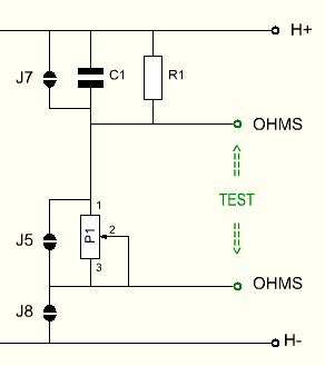
- Measure the value of P1 between the two 'TEST' points.
- Do not measure across the test points, with J8 closed, as this would magnetize the transformer.
- At the empty position of R1, place a new resistor which equals the value of P1 plus the old value of R1. So if R1 was 10k, and the potmeter was 90k, the new value of R1 becomes 100k.
- C1 is not inserted and J7 is open.
- Close Jumper J5. Verify if the 'TEST' points indicate a SHORT now. This is good.
- Verify R1 by holding the ohms meter between H+ and one of the two 'Ohms' Test Points (it doesn't matter which one). The ohms meter must read the new value of R1 now.
- If done, close jumper J8, and R1 becomes active.