Electron Engine ™
Printed Circuit Boards by Emissionlabs
EE21 + EE23 Gold Plated Board V7.1. for Input Applications.
For LL1588, LL1592, LL1690, LL1674, LL1676, LL1681, LL1684, LL1922, LL1930, LL1931, LL1933, LL1940, LL1941, LL1943, LL1948, LL1949, LL1971, LL5402
Attention:
- Some transformers need EE21, some need EE23. They way to use them is the same. Difference is only the pin out of the transformer.
- Overview
- MC Applications
 Input Applications (you are already here)
- Output Applications
- All Connection Schemes, Complete Overview
- Unsorted Application Information

EE21 Order Nr: 310-021-07

EE23 Order Nr: 310-023-93
EE22 is optional, and can be connected to EE21 or EE23.
EE22 Order Nr: 310-022-29
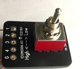
EE22 allows to switch externally between the two gain factors. This is an interesting option for moving coil. Just choose the sound like like most. For input applications it gives a "high gain" or "low gain" input. For output applications it gives a "High Signal" or "Low Signal" output. For stereo applications you need 2x EE22 boards. A High Quality switch, with internal contacts of solid silver is included in the price. When using EE22, the solder bridges "High" and "Low" on EE21 or EE23 has to be open.
Read the information below here, or go directly to the applications:
LL1588 Application
LL1592 Application
LL1674 Application
LL1676 Application
LL1690 Application
LL1922 Application
Part1. Create Balanced Inputs, with or without gain.
The different windings ratios of the transformers are used for:
- Gain (Step up the signal)
- Lowering the output impedance (Step down the signal)
- Break Ground loop, or splitter (Leave signal ratio 1:1 or 1:1+1)
So as you see, the above are three totally different things. There is a overlap with what each transformer can do, because of wiring schemes, and possibility to reverse the transformer.
Gain function. A transformer creates gain free of any noise and hum, and a distortion level better than any electronic circuit can do. At low signal level you can never beat that with electronic circuits.
Power Amplifier design. If the driver stage design Also if a driver stage has 'almost' the required gain, do not add another tube stage, and get stuck with too much gain and noise. Just add a step up transformer and the EE23 board.
Break the ground loop. This is a too difficult explain here quickly, how it works. Fact is, ground loops always occur, when a signal input is unbalanced. So RCA, and one signal is against ground. It is the whole reason why balanced (XLR) inputs are used in the first place. With XLR, signal is not against ground, but it is the difference between TWO signal wires. A transformer can do both. An XLR input can be added, OR an existing RCA input can be modified to become balanced. Doing the same as XLR, without having to change the amplifier chassis to XLR connectors.
Input |
Board |
Low |
High |
Core |
Characteristic |
| LL1588 | EE23 | 1x |
2x |
Mu Metal |
Brother of LL1684, but LL1588 may have a small DC component, for instance with a DAC. Board may also be used reversed, to get attenuation. |
| LL1592 | EE23 | 1x |
2x |
Mu Metal |
Neutral sound, High Signal. Board may also be used reversed, to get attenuation. |
| LL1674 | EE21 | 4x |
8x |
Amorphous Cobalt |
Medium Impedance. Board may also be used reversed, to get attenuation. |
| LL1676 | EE21 | 2x |
4x |
Amorphous Cobalt |
High Impedance. Board may also be used reversed, to get attenuation. Best Sound of Amorphous. |
| LL1681 | EE21 | 13x |
26x |
Mu Metal |
Much preferred product by professional users. Has internal shield, for very low hum. |
| LL1684 | EE23 | 1x |
2x |
Amorphous Cobalt |
High Signal Level. Brother of LL1588, but no DC component allowed. Best Sound of Amorphous. |
| LL1690 | EE23 | 1x |
2x |
Amorphous Cobalt |
Best Sound of Amorphous. |
| LL1922 | EE21 | 4x |
8x |
Mu Metal |
Neutral sound. |
| LL1930 | EE21 | 5.8x |
11.6x |
Mu Metal |
Designed for parafeed pre-amplifier output. |
| LL1931 | EE21 | 8x |
16x |
Amorphous Cobalt |
Wound with 6N 'Cardas' wire. Best Sound of Amorphous. |
| LL1933 | EE21 | 8x |
16x |
Amorphous Nickel |
Wound with 6N 'Cardas' wire. Also amorphous sound, but cleaner as cobalt. |
| LL1940 | EE21 | 4.5x |
9x |
Mu Metal |
Attenuating Transformer. For Output Signal. WIth Faraday shield. |
| LL1941 | EE21 | 16x |
32x |
Amorphous Cobalt |
Wound with 6N 'Cardas' wire. Best Sound of Amorphous. |
| LL1943 | EE21 | 16x |
32x |
Amorphous Nickel |
Wound with 6N 'Cardas' wire. Best Sound of Amorphous. |
| LL1948 | EE23 | 1x |
2x |
Amorphous Cobalt |
Wound with 6N 'Cardas' wire. Best Sound of Amorphous. |
| LL1949 | EE23 | 1x |
2x |
Mu Metal |
Attenuating Transformer. For Input Signal. Neutral sound. |
| LL1971 | EE21 | 12x |
24x |
Amorphous Cobalt |
Wound with 6N 'Cardas' wire. Best Sound of Amorphous. |
| LL5402 | EE21 | 1x |
2x |
Silicon Iron |
Very low impedance output |
Reading all data sheets is only confusing. Better is, from the ABOVE, make the preliminary choice of the transformer, and then final choice becomes easy. For instance for a high impedance input, there is LL1676 or LL1588. Do you want amorphous core? If so, LL1676 is the answer. For mu-metall, the answer is LL1592.
Inverted or None-inverted signal?
Ideally, an amplifier should not invert the signal, but amplifier manufacturers pay little attention to this, because they regard the product by itself. However an inverting amplifier can cause instability problems. Perhaps it happened to you, when removing the input cable, with the amplifier on, it responded with an very loud, very short whistle noise. That is such a case. Yet because few designers know about this at all, 50% of the amplifiers invert the signal. In case of adding an input or output transformer, simply check if the amplifier perhaps inverts the signal. If so, phase reversal at the transformer is recommended. It's what this option is intended for. There is no obligation to use it, but it is better. More information about this.
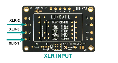
Creating an BALANCED input
I recommend this as a standard for tube amplifiers, by using the RCA (Cinch) input for this. Like this it stays compatible with all existing equipment, using the RCA (Cinch) connector, but there it creates the advantage of a hum-free, balanced input. More information about this. For this, an isolated ground type RCA (Cinch) connector has to be used, such as the Yamamoto.
Hint: When connecting a balanced RCA (Cinch) connector, even an XLR connector can be connected in parallel to it.
Fake XLR inputs
It is so sad, I do not like to say this, but several amplifiers manufacturers, some with great brand names, presenrt fake XLR inputs. Totally fake, and they fool the users with it. It is clear why they do it, because a real (balanced) XLR input costs a pair a transformers, or additional electronic circuitry. And users know, XLR is professional, so it makes them feel good. Well it's a shame actually. What happens? The manufacturer buys a 1$ XLR connector from China, and internally dumps the XLR-3 signal in a resistor. So the signal is only used from the XLR-2 line of the balanced pair. This a fraud to my opinion, but please regard it my opinion only. The situation is however, such an amplifier has the appearance of the XLR hardware at the outside. So specially here, using the EE21 board for instance with LL1588 or LL1676 in 1:1 configuration is the BEST you can do. It creates a real, balanced XLR input.
Even so you can save some money, and use the EE31 board too, which is very basic and it can also create XLR inputs.
Hint: When the EE21 or EE23 board is used, and connected 'balanced', an RCA (Cinch) and XLR can be connected in parallel. For this, an isolated ground type RCA (Cinch) connector has to be used, such as the Yamamoto.
Termination Network
A termination network is not mentioned in most Lundahl datasheets, when the transformers have no electrical error in the audible range. Above 20kHz, at some point some roll of begins. This comes in earlier if unsymmetrical used.
A termination network will make most transformers linear up to a higher frequency. Some types perform best with an RC network as load. Some other typed need only a resistor, and some need no termination at all. For this reason, a variable resistor allows just try it out, and also switch the damping on and off with Solder Jumper J8, to hear the effect. More information here.
Part2. Termination Network (also called compensation)
When an RC termination network is mentioned the Lundahl datasheets, begin with just using this, and it will work very good to begin with. Some data sheets do not specify such a termination, but when we read the data sheet carefully, and it can be seen, a load of for instance 10k Ohms was used achieve the data sheet results. Now this is normal, because without any load at all, any tone transformer will self-resonate at some high frequency. In HiFi there is no requirement for very high impedance inputs. Only historically speaking, the old 47k requirement for RIAA amplifiers is still a good value, and it is a de facto standard. For other signal inputs it is definitely no need to use "47k" and you will hardly see this any more. To my opinion 10k is much better, this is not a difficult load for any normal signal source. This value is commonly used by Lundahl, and others.
Important is: Several tone transformers require a minimum load of 10k. If the pre-amp which it gets connected to, has 50k to 100k of it's own, that doesn't matter. If 10k is connected to the transformer, the total load will some 8k. So then we have achieved the minimum load of 10k, as intended.
Roll-off. A good tone transformer has no amplitude error, and no phase error in the audible range. Yet at some higher frequency, somewhere between 35kHz to 250kHz, roll of begins, or resonance will occur. Such that show earlier roll of, may not show resonance. If symmetrical used, generally the frequency range if (the same) transformer is a little better.
Termination network. This will make most transformers linear up to a higher frequency. Along with change of amplitude comes always a phase error as well. Personally I find the last more disturbing as a loss of amplitude outside the audible range. But since this comes always together anyway, best is to linearize the amplitude behavior, and like magic, the phase error is gone as well.
Some types perform best with an RC network as load. Some other typed need only a resistor, and some need no termination at all. For this reason, we use a variable network, which gives us many options to use it, and a variable load resistor. This allows just try many things out, and also switch the damping on and off quickly just with one Solder Jumper (J8), to check if there is an audible effect. More information here.
The termination network is universal for all transformers.
Depending on the application, only specific parts, or no parts of the termination network are used.
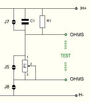
- J8 activates or disables the termination.
- J7 disables the RC network R1-C1 (to use only the potentiometer).
- J5 shorts the potentiometer (to use only R1-C1)
- A fixed resistor could also be used instead of P1.
- Open J5 and J7, to use both Potentiometer and R1-C1.
Using this Board.
- Close J2 to achieve 1 :1 transfer. Already now the board must work, and you can check if this is so.
- A good grounding scheme and best gain has yet to be chosen.
- Not needed, but sometimes better, is to use some termination components. This is done all at the end, when the board basically does what it is supposed to do, just not fine-tuned yet.
- The Input side has has letters L+ and L-1.
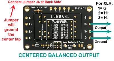
- The output side has letters H+ and H-, it has the termination network attached to it.
- On the board itself, input and output are floating. Normally, we need ground the board at the amplifier side. So no matter if used as sender or receiver, always the wires that go out of the cabinet are the floating wires.
- All four 'G' connections at input and output side are the same, and connected to the transformer metal, as well as both board ground planes (there is a ground plane on each side). So these are the best possible "hard" ground there is, free of induction. It doesn't matter which of the G connections used for this. There are a total of four, so to make shortest links, or to connect a load resistor to, or whatever you want to use a ground connection for.
- In addition, J6 centers the L-Side, (the input). This is only possible at low gain).
- J4 centers the H-Side (the output) . This is always possible.
Experiment with both gain factors. Basically it must work absolutely free of problems. The solder islands of the boards are very good quality and will not damage easily.
When it works all good, and the best sounding gain is chosen, the best termination network has to be found. A network is not always needed. Some applications like parafeed or other attenuating configurations work without it.
Optional: Some people do not like a variable resistor in the sound path, and it can be replaced by a fixed resistor. In that case, the variable resistor is shorted, and has no function any more. It can stay in, for later experiments. However to find out it's best value, the variable resistor has to be used. The way to do this, is as follows:
- It is assumed the board is good working, and P1 is adjusted well.
- Open Jumper J8. In this condition, an ohms meter can be connected to the 'TEST' points.
- Do not measure across the test points, with J8 closed, because the DC Test current (1mA) from the ohms meter may damage the transformer.
- Now the value of P1 is measured.
- Replace R1 by a resistor, which equals P1 + R1, and close Jumper J5
- Verify if the "TEST" points have zero ohms now, and Close Jumper J8
APPLICATIONS BY TRANSFORMER TYPE
Application with LL1588This is a neutral transformer, giving a gain of 1x or 2x. Yet by reversing the board, an attenuation of 2x can be achieved as well LL1588 is universal. We see it often used in DAC applications. LL1588 has a mu metal core. This material will not be permanently magnetized if there is some small DC current. (Though this DC current is not specified). |
||
Gain |
Termination of LL1588 |
Jumpers |
0,5x |
Attenuation needs no termination. To obtain attenuation, the board has to be used reversed. For this, "H-side " becomes the input, and "L-side" the output. Connection Scheme |
J1, J3 |
1x |
J2, J8 | |
1x |
With Fixed network C1=4n7, insert 1k resistor instead of P1, vertical mounted, in Pins 1-2 of the potentiometer. Pin numbers are indicated at back side of the board. |
J2, J7, J8 |
2x |
J1, J3, J8 | |
2x |
With Fixed network C1=4n7, insert 1k resistor instead of P1, at Pins 1-2 of the potentiometer (indicated at back side of the board) |
J1, J3, J7, J8 |
Adjustment procedure for best response of LL1588Lundahl does not mention the use of an RC compensation network, and the transformer can of course be used without. I found frequency range is 100% linear in the audio range, and very far outside as well, without compensation. For commercial applications, or parts count reduction, just use the transformer alone, and this is really a very good way already. Using it with compensation is just for getting the ultimate result out of it.
|
||
Reversed connection (For attenuation)
|
||
Normal (forward) connection)
|
||


Application with LL1592 and LL1690 with EE23 BoardLL1592 data sheet
|
||||
 |
||||
Note for LL1690Due to the different pin arrangement on LL1690, it fits on the PCB with the Text "LL1690" upside down. This is normal. This also mirrors the pin connections, wich is possible to do, because input and output are identical. |
||||
Serial 1:1 connection (Above Picture 1)
Phase Splitting for 2: 1+1 input (Above Picture 2)
Phase Splitting for 1: 1+1 input:
Fine tuning / Termination.
|
Application with LL1922This is transformer for creating gain of 4x or 8x. |
||
Gain |
Termination of LL1922 |
Jumpers |
8x |
J1, J3, J8 | |
8x |
With Fixed network R1=47k |
J1, J3, J5, J8 |
4x |
J2, J8 | |
4x |
With Fixed network R1=47k |
J2, J5, J8 |
Adjustment procedure for best response of LL1922
|
||
Application with LL1674 and LL1676These are two very classical Lundahl transformers for impedance matching, or 1:1 LL1974 is intended to convert 10k to 600 Ohms, in both directions, using it 4:1 LL1976 is an isolation transformer and can be used as a 47k impedance input (1:1) or medium impedance input (1:2), converting 10k to 47k. Please note, almost every HiFi source can easily drive 10k. Most sources have just a few hundred Ohms itself. |
||||
Gain |
Termination |
Jumpers |
||
Single Output, impedance matching No Parts mounted. |
4x |
600 Ohms in, 10k Out. (Can be reversed) | J1, J3, |
|
Phase Splitter Output No Parts mounted. |
4x |
Source must be 150 Ohms | J1, J3, J4 |
|
High Impedance (47k) input No Variable Resistor mounted. |
1x |
R1=33k | J2, J4, J5, J8 |
|
High Impedance (47k) input |
1x |
R1=4k7, R2=100k, adjust R2 for best square wave response | J2, J8 |
|
Medium Impedance (10k) input No Variable Resistor mounted. |
2x |
R1=68k | J1, J3, J5, J8 |
|
Medium Impedance (10k) input |
2x |
R1=10k, R2=220k, adjust R2 for best square wave response | J1, J3, J8 |
|
|
||||