TESTING THE AMPLITREX AT1000 TUBE TESTER
Just received the first of two, today, excellent packed, fast shipment service.
DISCLAIMER: The following text is my own opinion, please read it only as such. If there are any mistakes or errors, that is because the following represents indeed only my personal opinion.
Problems I had with it. As far as I recall, the Amplitrex 1000 has been introduced in 2004. So I waited a while buying it, just to make sure I didn't buy early versions of it. Unfortunately this did not fully work out as I hoped.
 #1 Test Table - Grid Voltage wrong for DHT tubes.
To my personal opinion, there is a hardware related problem with the software of the AT1000. This problem is only with directly heated tubes, because the AT1000 connects one end of the heater to ground and the other end to the DC heater voltage. This lifts up the heater center with half the heater voltage. This may not seen relevant, but it is. With Directly heated Tubes (DHT) there is no electrode for the cathode connected to the outside world, such as with indirectly heated tubes. Still, we have to take the heater center as the reference point for the cathode voltage, and not one of the two ends. Problems come now, if we have to apply the negative grid voltage.
Best is to use a numeric example. Suppose you have a 2A3 tube, the ideal 2A3 pulls 60mA at 250Volt, with -45 Volts grid. You can look that up in any datasheet ever made, the are all the same.

Cut out #1 from the original RCA datasheet
The next cut out shows where the grid voltage is referred to. So it is definitely not referred to ground, but to the MID-POINT of the heater.

Cut out #2 from the original RCA datasheet
Let's not start asking WHY that is. The datasheet is 70 years old, and we must accept it was defined that way and no other way. There are no datasheets which define that you have to measure the 2A3 DC heated, and refer the grid voltage to ground. Besides if you do, it makes one hell of a difference if you apply +2.5V to the heater or -2.5V. At positive heater voltage a new 2A3 will draw 13mA LESS than at negative heater voltage. Now, neither positive or negative heater supply is defined in the original datasheet anyway, so let's not get confused by this. Of course you CAN easily measure the 2A3 with +2.5V DC heated, BUT you are supposed to measure 60mA still. Reason is, this is the SAME tube, and a DC measuring method was never defines by RCA. So to get the same result, you need to apply a less negative grid voltage as -45V. You need to apply -43.75 Volts, to be precise. This problem was pointed out by me, to AMPLITREX, and they have changed the tube data tables indeed. So where it was written -45V, they changed that to -43.75V, and there you are: 60mA. Besides, and very important, only at 60mA you can measure the transconductance and compare it with the datasheet value of 5.25 mA/V.
Still this prints out the test results wrong!
So suppose you have a bogey tube. Such a tube is one with data as in the cut out #1 (above here)
You apply -45V grid at 250V plate, and it will draw 60mA. This data is final, there is no other.
Now the Amplitrex prints the following result in the computer mode:
Plate Voltage 250V
Plate Current 60mA
Grid Voltage -43,75V
The patch with changing the tubedata.csv table will correct the plate current to the right value, but the grid voltage is represented WRONG still.
And again, there IS NO DC method for testing the 2A3. So the DC data would need to be corrected in software for getting the AC Results. Man, this would have been so easy! Just let the -45V in the test data table, and add half of the filament voltage to this in software. So -43,75 is effectively applied to the tube (DC heated) and that would give the same results as AC heated.
#2 Curve Chart, all grid voltages are wrong for DHT tubes.
The above situation leads also to WRONG data of the tube curves (in the computer mode). So with the RCA 2A3 you must program the tester for these values:
Grid Voltage, 0V, -10V, -20V, -30V, -40V, -50V, -60V, -70V, -80V.
Indeed these values are printed by the Amplitrex on the curve sheet. However, in reality, the grid voltages used are:
Grid Voltage, -1.75V, -11,75, -21.75V, -31.75V, -41.75V, -51.75V, -61.75V, -71.75V, -81.75V
The problem gets very visible with the 0V line. With triodes, this line starts in the left corner. ( So at 0Volt Plate, 0mA plate current). The 0V line of the Amplitrex starts at where you normally have -1.75V
Also due to this problem you are not even able to draw the 0Volt line, because you have at least half the grid voltage
I heard from other users, a patched tube date table exists, but actually myself I was never send it. I call this a problem, because I expect an update unsolicited if they have an error in the data. Even Microsoft does that. For me it is not a problem to patch this myself, but it is proof they don't send out updates, even when they know there are errors, and they know they have to send an update to everyone.
What is so curious about this, this problem was brought up to Amplitrex because people read about it in my website. Obviously they did not send this information out to users, because:
To say this in another way: I never received an update. Never.
The patched tube date table is easy to replace when you use the tester in the computer mode. Just replace it on your PC and you're done. However, it is a very risky thing to replace the (same) table inside the tester. If this goes wrong, for instance at a power down in your house, or the data connection to your PC breaks down, Windows stalls, or whatever mistake happens, you MAY damage the internal software completely, including the possibility to restore it. I had stalled connection indeed. So at some point nothing happened any more, and I could not stop it either. I ended up with switching the power off, but I was lucky the tester still worked. The second attempt worked out, but I am not going to repeat this any more.
Most people I know, do not use the tester together with a PC. You can't tell those people to do a firmware update to fix manufacturers errors, and say if it goes wrong it's their personal problem. These people to my opinion have a legal right for a free update, in house at Amplitrex. And yes the firmware update is risky, I almost killed my own Amplitrex with it. When I am not mistaken, the patch was made end 2011. So we talk of testers that were send out before that.
#3. AT1000 cannot print pentode curves. It is really so!
The PENTODE curves are printed TRIODE MODE. The Amplitrex website said it can test pentodes. This is simply NOT TRUE. Being able to test pentodes in Triode mode, is very nice of course - as an option. However, it gets quite strange if the pentode mode is missing from the software completely. . To my opinion, not having a pentode mode for pentodes is the next blooper. ANOTHER one of those things, that requires a fix, and a free update unsolicited.
#4. So called "Emission Test" is not what the word suggests..
I disagree with what they are doing here. Tube Emission is not measured the way it is done here. An Emission test is done by trying to draw a current with the tube, in diode mode. What is done by the AT1000 is measuring normal DC current in triode mode for all tubes, and this is compared to the datasheet value in percent, and then call it emission in percent. Sorry, but this is NOT the emission. A tube with 80% plate current can easily have 120% emission. This 80% plate current is called 80% emission by the Amplitrex AT1000, and we may be having a 120% (REAL EMISSION) tube on the tester. This is a real blooper also.
#5. Cooler fan is definitely much too loud.
It is such a relief to turn off the Amplitrex, and that loud fan shuts down. Pffff :) .
#6. Transconductance results in fixed bias mode is a WRONG way to do such tests.
This is not a specific AT1000 mistake, I see it with almost everybody who puts some numbers together. Transconductance is represented by the AT1000, in percent. Now that may LOOK nice, but percent is a relative number. So when you say 70% it means nothing. Though you might think it is 70% of ideal. But Gm is a very flexible number, it depends on what you do. So now you think: ok, so we do it as we are supposed to do. Yes, but how is that supposed to be done? Tube data sheets were all made 70 years ago. So what counts is what was written, and not what is babbled in the forums. I give this clear example for a 2A3 tube. It says in the data sheet, under Average data: Anode Voltage 250V, Anode Current 60mA, which is achieved by a grid voltage of -45V as an average. And no, you are not supposed to apply -45V to the grid, and voila plate current appears in percent. This is silly, and wrong, and you will find this instruction in no tube data sheet.
So what must we do to achieve that 60mA, the data sheet writes. Apply -45V to the grid, which would be exactly right for an average tube. But grid voltage is subject to great tolerance, also for new tubes. Meaning: What must you apply, when the tube is not average.? We don't know! Because that's what a tube tester is for. So perhaps you need -41V. Or -50 or -53V. Whatever it will be. That is what you have to take. And then, and only then you get 60mA. So let's say a random tube needs -41V to produce 60mA, and transconductance at 60mA is as average. 5.25mA/V as it writes in the data sheet. So if a tube has this 5.25mA/V, then (and only then) it has 100% transconductance. This is easier to misunderstand than to understand.
Of course it can be meaningful to test tubes in fixed bias mode, because some (seldom recommended) circuits are doing so. And then it's intelligent to test with fixed grid voltage. In all other cases it is nit so intelligent, rather wrong. So yes you can come up with a plate current with fixed grid voltage,.for instance being 80% (of 60mA). So 48mA. That is fine. But it becomes dead wrong writing on the AT1000 display that 48mA is the same as 80% emission. Really, who writes such software, has not understood how tubes really work. Sorry for the hard wordings. But this is one of the most disturbing mistakes.
Bug #9. Test program stalls when you press the "TEST" key twice.
When you have a test running, and by mistake you hit "start" a second time, that ends your work. The software stalls after 10 seconds with a message about an "RS232" problem. Then, if you try to re-start the program nothing happens. Reason is, you will find in the Windows Task Manager. The program has stopped responding, but is still running. So you have to kill in manually, or re-boot your PC, as a punishment for hitting the test button twice
Bug #10. The grid voltage is advertised like this:
"GRID (G1) SUPPLY: 0 to -99.9 VDC, in 0.1 V steps (-150V in Auto Bias mode)"
However, when I try so with my AT1000 testers, G1 cannot be set to 0V. It starts at -0.1V instead. For myself this becomes a big problem when making tube charts, because I have to set the grid step for instance at -10V. So I get -0.1V -10.1V -20.1V etc. Very unusual values. Then if I forget the zero volt curve, I can start at 1V, but then you get -1V, -11V, -21V, etc. Again not nice. In reality you have to skip the first curve if a series, and that is also not nice. So I can test from -10 to -99.99. Most of all it was advertised as 0 to -99.9 VDC and that's simply not what it is. VERY BAD.
Software Features: You should read the link at the bottom of this page, where the Amplitrex is compared with a 20 years old digital SOFIA Tester. This compare shows the strengths and the weaknesses of each of the two. This is nice because you will see now, what two different companies did, while trying to achieve the same. I can't find any of the goodies of the Sofia software in the Amplitrex functionality. Which is a real pity, because the SOFIA Software -even today- has amazing functionality, myself I like it more than the AT1000 software. Well but the SOFIA is not made anymore. I keep mine on a safe place, and use the Amplitrex as the workhorse.
Bug #11 Printer problems.
The curves charts are generated by the build in software, for printing in the top-left corner, and a HORIZONTAL page. ( So a rotated page). However, there must have been some confusions with USA and European printer settings, because when I print it here, it prints the image too close to the edge. This is only so for the curve charts. The table with test data is printed correct. This issue would have been solved automatically, by adding a small blank area to the charts. Well with (another.....) work around, we can work around this. What is more difficult, the charts are AUTO SCALING and I can't get this terrible feature switched off. I hope is (another.....) work around, but I wasn't able to find it, and in the manual there is nothing mentioned. The problem is, when I plot the charts of two tubes which are almost identical, still in plots for instance the one tube with a scale of 55mA and the other with a scale of 60mA. Then -of course- the buyer of those tubes lays the charts on each other and holds the pages against the light, and then complain to me about bad matching. So to prevent this, I need to try to fiddle around with the test tube settings until by coincidence the charts have the same scales. I can tell you that can drive you crazy sometimes, but I am usually successful with just two tubes. You never get it done with a series of 30 tubes of course.
Here you see for instance two fully identical NOS RCA Tubes. Tube1 - Tube2
The Amplitrex produces tube charts, one with a 50mA scale, the other with a 60mA scale. The reason is unclear to me. Chart1 - Chat2. For your interest, you should print those two curves and lay the pages on each other. You may not believe the tubes are identical, yet the are. In the end, what use is the explanation, when thee is no solution.
Bug #12. Chart Plotting works only, when the PC is
set for USA number format.
To personal opinion, this is a case of improper behavior. Amplitrex knows, I an located in Germany, and sends me software which only can plot curves when I set my PC to American number format. So not only the Test software, but my whole PC. And then of course many of the things in Windows begin to fail, like my Excel program and whatever. I call this extremely arrogant, and not just a bug. It's a non-working part of the software.
The USA format is. 10.5 mA, the European format is 10,5 mA. So a comma instead of a point. Now, the whole software assumes you have a USA computer, and if you don't (such as with me, I am in Europe here) the program will not plot curves. So before you start the AT1000 software, you need to set your PC to American number format. By itself not a problem to do but...... for just in case you do multi tasking, so use another program which uses numbers, this program now uses the USA method also. So your Excel won't work, Paypal and banking software makes mistakes when you enter numbers etc. Who does this is a fool, and you should never, not even shorty, set your PC to American number format when you are in Europe, or vice versa.
For my own safety, I use now an old PC for my two AT1000's, and set this to USA number format. THIS IS ABSOLUTELY KNOWN AT AMPLITREX.
#13. You can be superstitious or not, but it is Nr. 13.
This problem comes from the A/D converter having only two resolutions, 10mA and 160mA. This is really troublesome when you have 9,5mA tubes, and you test them by the settings as supplied by the original Amplitrex tube test data.
The real problem is: A/D CONVERTER OVERFLOW IS NOT DETECTED. It clips at 10mA, and the maximum value of 10mA is simply used "as is" even if the tube was pulling more than 10mA. I had a severe case, of a good tubes can be reported "bad" but in fact what is bad is the software, and there is nothing wrong with the tubes!!!!!
|
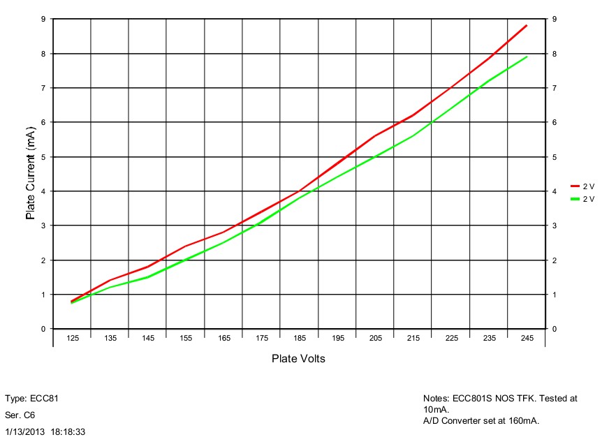
Click on the left picture, this is a NOS ECC801S, right out of the box, and I removed the cellophane myself. According to the AT1000 this tube is bad. The plate resistance must be 11k, and this tube has 31.2k and 20.8k. Definitely much too high, and such things happen only if the emission is too low. But... too low emission for a NOS TFK tube? So I plotted the tube curve. Fully normal, and low emission tubes can be seen from that clearly. Besides the transconductance is as it should be, and nothing wrong with the bias too. So this defect just sort of makes no sense. I suspected an oscillation with the tube in the tester, because ECC801S is a pretty high gain tube, and yet 10mA is not a really low current. So I set up a scope, but no oscillation. So I tested, and re rested, took some other tubes, until suddenly I found an that had a gain of 340 on the one system and a gain overflow on the other. (gain was <500k it said). It took me one hour to find the problem, or almost certainly what I think is the problem. |
|
I set the A/D converter to 160mA (instead of 10mA) . Now the problem is gone! Is it really? No! So now we work in a resolution area (160mA) where you cannot test such a tube accurate. So the test table SEEMS good, but again it is a bad result. Why I say that? Look at the curves below the table, it shows what the tester is REALLY doing. It is clear, the thing is working at unacceptable low resolution. Yet the AT1000 blindly produces a nice test table, and all seems fine. (But it isn't) How can that be? Well... supposing the problem is as I expect, there is an overflow with the 10mA setting of the A/D converter. So it i set for 10mA static in the beginning. Somehow the measurement of the plate impedance and /or gain is doing something that makes the 10mA A/D converter clip. That is kind of natural because it is set to 10mA and the tube is biased at 10mA. So far so good, and you can say it was my own mistake. What I do not understand, why is there no software warning on a clipping A/d converter. If there is an overflow bit present somewhere, it should be used and not ignored. Even if there is no access to this (inside the chip) information, the software can easily recognize my error. Same as I should "know". Only thing is, I am no machine and the AT1000 is. |
So to say it again, I was just using the tester with it's standard ECC81 settings as provided originally supplied along with it. To solve this issue, you need to operate 1mA below original settings, AND use Auto Bias, so to prevent the A/D converter clipping problems, and then, finally the problems are gone. If you do not understand the above, I am not surprised, I took a long time myself to find the solution too. I rejected many bad tubes in the beginning, trusting the Amplitrex, distrusting the tubes. I should have done the other way around. Arrghhh!! |
|
#14. Not a real Problem
This one is not a real problem, but I want to mention it anyway. After doing every test, the configuration settings pop up as a separate screen. Probably for in case you might want to print this or so. Personally I find this very annoying if a new screen pops up EVERY TIME, and all I do is click it away EVERY TIME, and it would be better to have a software key "show configuration" to make it pop up, and for the rest not annoy me. There is no work around, since the software chooses a fixed position (RIGHT IN THE MIDDLE) of the screen. So if you shift this stupid menu in a corner, that doesn't help, because after every test, it pops again in the middle of the screen, where you don't want to see it. A man.... after every test it pops back. So I suggested to Chris Terraneau not to set the default position in the middle, but let that menu screen where it is. So that works for Chris quicker than adding a soft key, which he also needs to explain the function of, in the manual etc. Shifting the menu in a corner is a natural reaction for most users that get annoyed by it. Then all the software needs to do, is LEAVE it there. Needles to say, this idea was not followed up on, and for me that was the last time I send an improvement suggestion, as he never does anything with it anyway. I rather put the things here, I hope Chris reads what others can read, and perhaps he finds that more inspiring than privately send messages ;)
#15 The number of curves when plotting tube curves created a mess
When using the SOFIA, you can plot only a chart with 11 curves or 21 curves. No other choices. Why it that? Well, if you take the maximum grid voltage for instance 20 Volts, any normal person wants steps of 2 Volts when plotting 10 curves, right? Are you sure? Because that is wrong! With 2 Volts per step, and going from 0 to 20, you have not 10 curves but 11. They never found that out at Amplitrex. So the maximum number of curves you can choose is 10. Meaning it divides the number 20 by a factor NINE. So get nine steps of 2.22 Volt. Or, you can take 8 steps of 2.5V (Which works....) or 7 steps of 2.85 Volts. Most of the time you get chaos. That is the one and only simple reason, SOFIA has only 11 curves or 21 curves. Any other number of curves gives a mess. So can you take 11 curves withe AT1000 then? Nooo.... you can not :( The maximum is 10. To make the chaos larger, the curves will not start at 0V but at 0.1V. What a mess. So when you have 20V, and take 10 curves, you get 0.1, 2,21, etc
The work around is to have the curves start at an end value and start value, such that it begins at a normal number, and takes normal steps. Like here start at 2V, and take 9 steps of 2V. That will make the steps 2V as intended, and makes it end at 20V as intended. That may seem not difficult, but when you want to the plots to end at 35V it gives a mess again.
The solution is one of the many work around, but very tedious and extremely time consuming: For each and every tube type you want to plot charts, you have to create a set-up which gives no mess, and save this as "the" set-up for this tube. Since the curve plotting takes very long, and you need a lot of trial and error before it looks good, I avoid this like monkey plague. And then when I use my Sofia curve plotter: Bang! It works immediately, I need to try out nothing, and the curves are plotted in seconds instead of minutes.
What else so say.
I call it lack of interest. . In the beginning I have send software issues to Chris Terraneau of Amplitrex, hoping for a software upgrade, which he might be able to use as general improvement as well. All I can say is, I get always an answer in a really timely manner. Quite unusual today in the internet, and a +100% positive for that. Only in the end, all I get is another one of those work around recommendations, and never the a software repair. My personal conclusion is, Chris Terraneau is not interested in software improvements. I have no other way to express it. He is only interested in get you going with the way things are, and I must be fair, this is really what he helps you with very good, and very fast.
Yet we all know that software is always full of bugs and mistakes, and it means good software lives from continuous patches and upgrades. I never see that happening. You may have noted, I feel deeply disappointed by this.
The good part of it:
Don't get me wrong, I like the Amplitrex AT1000. It's just because in the internet problems come first, I took this order. Since overall the Amplitrex is a good product, it still received only four stars from a maximum of five. Having the AMPLITREX AT1000 is having good technology in house, and technologic advantage is what makes our company attractive for customers. So we always use best instruments we can find. If not, we 100% restore an old one. (see Restoration report about Funke W19 we use, and four "Kalibr L3-3" we use). We use a total of three AT1000. Two here in Germany and one in the factory in the Czech Republic. A fourth one is in use with our USA distributer. So Chris got over 10k$ business via us.
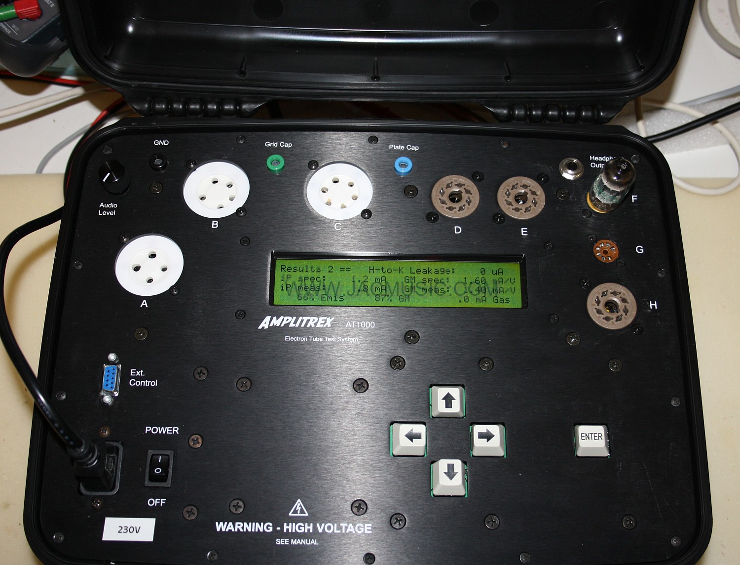
First impression. I unpacked the unit, plugged in the mains cable and switched it on. Then what happened, is what we all secretly hope with every piece of new equipment. I needed no manual and I could understand it "by doing". I switched on the Amplitrex, and the large display lights up and comes up with a digital "roll chart". Well, we have seen that before as paper version, so hey... I understood that right away! I just scrolled down to 6SN7, because I had one on my desk. I selected it, and then I expected having to look into the manual. I was ready for that. To my surprise the tester said: "put the tube in Socket E, and press "Enter". After I did so, the automatic test began before I knew it. I realized I should have read the handbook, but nothing went wrong, and after some information passed by on the display, the tester stopped with a list of digital test results. So, plate current, Transconductance, leakage, everything. I was so surprised having this result out of the box. Unbelievable! I took out the tube and compared the result with one of my L3-3 that are reference testers. All readings are identical. :)) A fantastic fast result.
Materials.The "feeling" of the tester is much better than it looks on the picture. The case is good quality and the deck plate is thick and heavy material, and the (few) sockets are good quality too. When I see how some of the old Hickoks look after so called "experts" and other idiots have worked with them for 40 years, I can tell you they really suffer. So this very rugged case for the Amplitrex is a very good idea and will withstand the "experts" for many years.
Tube sockets. The 9pin socket I think is too tight and it damages tube pins of some expensive ECC88. After I plugged in a NOS tube a few times, the pins look heavily used already :(
For the rest, tube sockets are fine, and even the (very dangerous) metal rivets of the Chinese UX4 sockets have been carefully insulated. Good job. There are not enough different tube sockets in the tester's deck, but fair enough, I knew that before buying.
Calibration: They do have calibration points inside, but there are several ways to check the voltages from the outside, so you can regularly verify that. Also since we use three Amplitrex we can compare one with the other. Mind you, the grid voltage has an internal series resistor inside, so you can only verify the grid voltage with a tube volt meter, or any other extremely high impedance meter. Mind you the regular 10Meg Ohms that almost all digital meters have, is too low. Or, what you can do, tap it from the inside, before the series resistor. (p.s. when you have two digital multi meters, you can test the impedance of one, with the other. Likely you will see 10 Meg Ohms)
Conclusion for Stand alone mode: When you are not so technical, and just need some quick good/bad results, the stand alone mode is what you need, and don't even think about computer control. However, this tester does not tell you when a tube is good or bad. This can be real problem for non-experts, and you MAY want to prefer a good old Hickok with a red-green scale. So with a Hickok the red-green scale is really reliable, I can tell you so. The Amplitrex says something about Emission in percent, and Gm in percent, However, it is not testing Emission at all, but plate current and just calls that emission. Which is a mistake in the software. Furthermore 20% below average Gm is not so bad as long as the tube heats up fast, and plate current is strong. Vice versa for low plate current. It is no problem when Gm is above average and heat up is fast. Some factory-new tubes can be that way. With some understanding of tubes, the stand alone mode is a very good one. Automatic leakage test and grid current tests are reliable, and switch off the tester in case you're trying to test a tube that is a problem perhaps for the tester itself. In the end you have similar results as with the L3-3, but without all the buttons and knobs and cards and knowledge you need for the L3-3. Here is the advantage of the Amplitrex It fills a huge gap on the tube tester market. Attention: I do see a problem with those "Gm=80%" result in fixed bias mode, which is misleading, and tubes cannot be that bad. To get the REAL picture, set it on auto bias. Well, what is positive is, the experts already know this (of course)
Conclusion for Computer control mode: This is actually why I bought it. However, this function is not very self explaining. A problem for non-USA users is, that you MUST set your PC to USA Region, or the software will make errors and/or crash. So to work comfortable, I used a dedicated PC for this and set it to USA Region. It is difficult to use database programs like Open Office (or worse: Excel), since problems arise where comma's and are used in Europe, where the USA uses semicolons and vice versa. If you ignore this, you mess up the tube data tables, and the software will stall, or produce weird mistakes while drawing tube curves. So to prevent this, I use now a dedicated PC, which I set to "USA" region. This sounds so simple, but having to use an PC, for the AT1000, is a cost factor, and it takes away real estate in the lab as well.
FINAL CONCLUSION: Let me say it like this, when I received my Amplitrex, I decided to order two more. I think that tells it all. Let me put it like this. The hardware is 00% top quality, and really without any issue. The software However, is a bit raw, just made two "work" and that's it. Not so much problems and errors exists, but because these are not followed up (to my personal standards of quality) these things may seem larger, if you are forced to see it, every time you use the AT1000. Many items were brought up to Amplitrex, and really a software repair should be possible. So far there is only a patch with the data tables, which is not regarded a decent software repair by myself. It is regarded such by Amplitrex, so let's just say we have another opinion about this.OVERALL RATING:
THREE STARS ***
Compare also with other digital tube testers