Since 1993 Copyright Notice
TEKTRONIX CURRENT PROBES
During my engineering studies which I finished in 1986, at the Technical High school Rotterdam, we had a Tektronix Current Probe in the Energy Lab, an A6302 (DC probe), with AM503 Amplifier in a TM501 mainframe. I can remember so well, because my graduation assignment was to develop a DC + AC capable, high current, high voltage, current interface from discrete devices. The challenge was all these requirements at the same time. I received a special praise, for the nice way it was build, and it's possibilities. I choose a concept to amplify the signal on the primary side, using a miniature power supply which ran on a 40kHz oscillator, and from there transfer a decent signal level with a magnetic isolation amplifier. So I was always the first one to grab the Tektronix, because it was my reference, and there is a picture of myself in lab, demonstrating the result to new students, at the open day. Recently, I acquired the same combination (6302+AM503) for my little private lab. Just out of nostalgia, but if you want to use a current probe for your HiFi stuff, P6019+134 Amplifier is my favorite recommendation.
You may find this Tektronix book about probes interesting. So far, only a few companies made good current probes. It is hard to combine sensitivity, frequency range down to DC, and up in the Mhz range, with good linearity, no damage at peak current, and no messy items on the bench. All of this combined in the right way, is hard to do. A good current probe is very difficult to build. Add to this, you can work around having to use a current probe in many ways, so this is only a market here. Yet, from a professional view, it seems weird, we all want to see voltages on the scope. But current we try to derive from other things we see. But deriving the current from other things we already know, isn't that the same as deriving the voltage from other things we already know?
A real advantage from a current probe, it hardly affects the circuit, unless we have Radio Frequencies. It doesn't need to open the circuit, and the measurement is kind of "differential". So it doesn't matter what is the DC or AC level to ground. There are no issues with ground level or shielding.
Please take this as my personal view only. I do not want to insult some of the truly genius designers, who need little measurements, and already know what they have in front of them. Like my late friend Roger Modjeski. For a normally good designer however, having to miss the possibility to visualize current is wrong to my opinion. All I can say, I was often surprized to see the wave shape.
Just to spark some thoughts: How would you measure the peak current though a tube rectifier with an oscilloscope? Do you know what happens if you exceed it? Just make a sketch of the measurement set up, and you'll see it's pretty nasty. Like where would you connect the ground lead of the probe (which is grounded to the scope chassis)? So yes, I can understand the temptation, to replace it by verbal logic. Like: "We never had a problem with it since 25 years, so the circuit is good". That kind of saying I heard often before, and it may sound pretty impressive. What is really means however, it was never tested, and they just knocked it together. That is not a good idea for beginners, and even worse for professionals.
The real problem is not, current measurements are not really needed, but some fools (like me) say something else. I think the problem is only, good current probes are expensive. The cheap ones are bulky and no good. Also they are happily specified for going down as far as "1mA" but the result is drowning in noise, when the equivalent noise is 1mA too.
 When you do not want to buy those special probes which can only be connected to proprietary oscilloscopes, there are no new products as far as I know, which are really useful. I think there is only vintage Tektronix for that.
Myself I am not interested in test equipment from no-name vendors. This is an interesting situation, because the Chinese seem to think so as well. They drain the market for the vintage probes from Tektronix instead. China is #1 development place for switched power supplies. You can say what you want, but the Chinese have found their justification in this market. This needs many good current probes, capable of high frequency and low current at the same time. So the Chinese drive up prices on Ebay for vintage probes like the 6302 easily up to hundreds of Euro, whereas guaranteed good ones, which little DC offset, can go for very high prices. Sometimes it seems to me, they just buy them "as is" and simply re sell the ones that are not very good. I can't blame them.
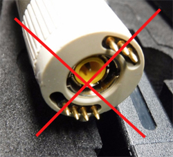
 Simple version, Chinese current probe. Bandwidth 1MHz.
I don't even look at it.
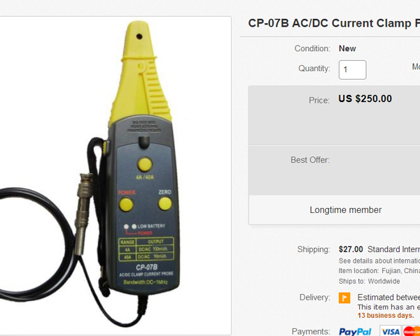
 Simple version, Chinese current probe. Bandwidth 50MHz.
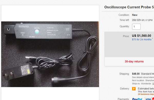
This one is obviously inspired on the Tektronix version. The mouth looks similar, just thicker, It has a de-gauss button, a DC balance potentiometer, same as the Tektronix has in the measurement amplifier which you need to use along with the Tektronix. What it does not have, is the Tektronix features, such as adjustable sensitivity, bandwidth cut off, and an AC/DC switch. Well fair enough, what is very good, the measurement amplifier is integrated, but for that the probe itself becomes a bit bulky, and you can not manoeuver it so nice inside a wired circuit like the Tektronix. The price is painful, and I would never pay 1560US$, and take the risk after 5 years it develops a problem, and you find out the company where you bought it, doesn't exist any more. I imagine how it is put together with self adhesive glue, which gets loose, or the foil cracks where the switches are underneath. Where is the service manual, like you can get from Tektronix? No, this is nothing for me. Not for 1560US$.
However, let's check the specs better. Noise is 1mV RMS,and sensitivity is 0.1V per Ampere.
So let's do an imaginary measurement, and you will see this item is a piece of sh....
We set the scope at 20mA/Div. The noise of 1mV will fill 5% of a division. That will make the electron beam look unsharp. What does it take now to display a wave form relatively good? . Sure that would be more than half of a division because otherwise it would consist for 10% of noise then. So lets's say we want two divisions of signal visible. At 20mV/Div of the scope setting, that needs 40mV on the scope input. So how to get 40mV out of the probe? At 0.1V per Ampere for the probe, that needs 400mA. So what do we get here? We see a 400mA signal, displayed with two divisions and 5% of a division noise. We can of course set the scope more sensitive. Let's set it to 5mV/Div. What happens now? Instead of 400mA needed for two divisions we need only 100mA, and 5mA/Div is pretty much where most scopes end. But how about the probe noise? It will be not 5% of a division anymore, but 20% of a division. It's a matter of taste, saying you can measure 100mA this way, but it it is not my taste, and not my way. So to my opinion, this probe only becomes useful above 400mA. Whereas my Tektronix probes work fine in the single mA range. That's why the Chinese search for old Tektromnix probes, and sell the new ones they make, to us. Very nice. What a crazy situation! But who is crazy? Not the Chinese!
Some vintage Tektronix Current probes.
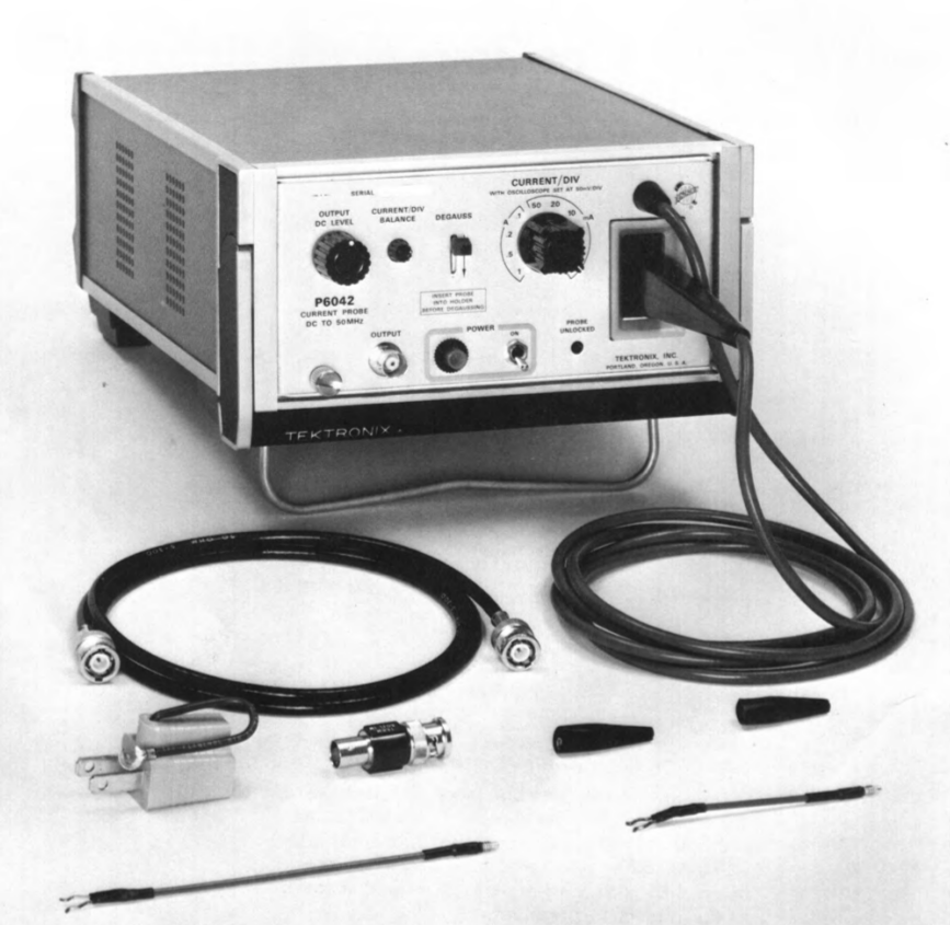
TEKTRONIX P6042 AC-DC probe
This is the first probe with AC and DC capabilities. The specifications are so excellent, I think there is still no comparable product. The heart of this Current probe is the magnetic sensor inside, which is an air gapped current transformer with a Hall Element in the air gap. So when the current transformer stops working at too low frequency, the Hall Element takes over. The sensor head is an AC current transformer, the Hall element is connected to the measurement amplifier, which does the biasing for the Hall Element, and the DC offset. The current transformer of the head, consist of a secondary winding, whereas the primary "winding" is the electric wire under test. So this acts as a single winding. For this reason, sensitivity can be increased by winding the wire a few times around. This can only be done if the wire is thin, and at low frequency. At high frequency, this would introduce a "coil" in the circuit under test. For DC and very thin wires, winding it 5x or so around the probe will simply increase the sensitivity by a factor 5.
This sensor was later used in the probes like A6302. Due to different DC offset tolerance, you can use any P6042 head in a 6302 probe, but only such 6302 heads with small tolerance in a P6042 probe. The sensor itself is not so exceptionally sensitive, not very linear, etc, but wow... the frequency range is so high. The good result comes from the analog circuitry in the P6042 amplifier. The P6042 is a stand alone unit, just connect it to any random scope, and you're done. The 6042 compensates all the unlinearity, and boosts the sensitivity to an impressive level. What I like about it, is the relatively small size for such a complex unit, and also what is quite handy, you can stick the probe inside when you are done. I think this was many times the life saver for the probe head, which is sensitive, and the Hall sensor can be damaged when you drop it. After a drop, you need to re calibrate the DC offset from the inside.
The Hall Sensors are also mechanically sensitive, as some people say because they are filled with a relatively hard epoxy resin, which intention is to protect everything, but it can also damage things. So a more softer filling compound may have been better.
Pro: Compact size stand alone unit. Fully up to date specifications. This is very remarkable due to it's age.
Contra: Compare it with the later A6302 probe which is essentially the same, but A6302 is only a probe. Whereas P6042 is a combination. Meaning with P6042, you cannot replace the probe head, there is no connector. The same applies for the amplifier So when the amplifier is faulty, you are forced to repair it no matter what. So you always have the unit combination probe + amplifier.
What probes to choose for AUDIO Applications?
Tektronix Current probes
The Chinese sweep this market empty. They use them massively for designing switched power supplies, which is their specialty. Supply is low and China is large. sometimes you see them offered from China on Ebay, You can say this is device they didn't want to have anymore. It will not make you happy.
This is no insider report, for those who know all about it, and are looking for more. This is rather if you ever thought of using a current probe for DIY projects, and don't know where to begin. At least I had this problem myself. It seemed quickly clear: Tektronix makes and made the best current probes ever. They are smaller and higher bandwidth than any others, and it seems to me the vintage probes are much sought after, though they are 50 years old or more.
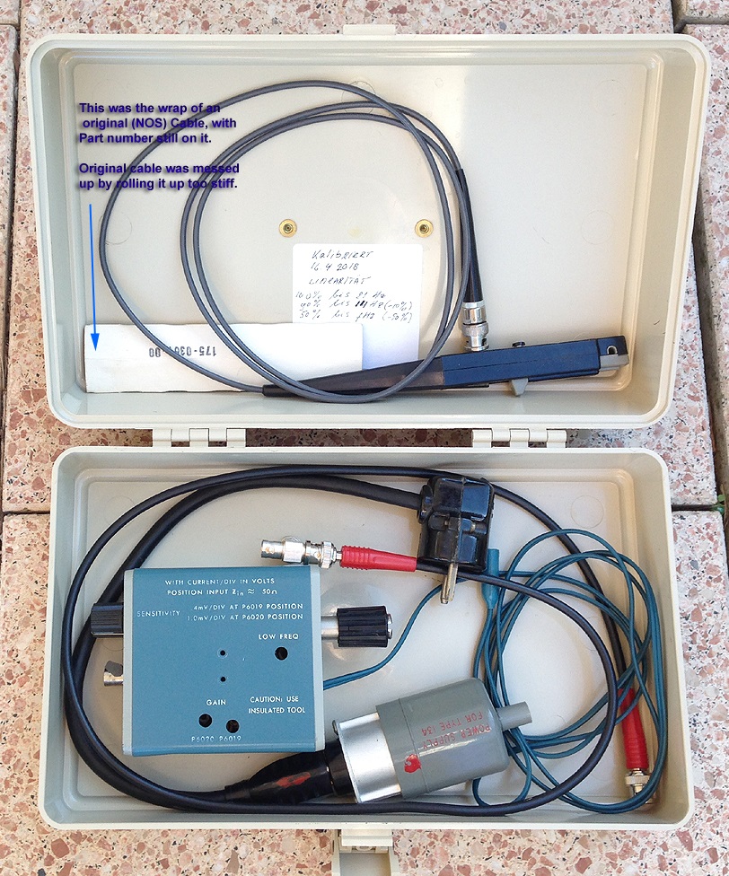
A probe should look not like an old tool, but like a carefully treated instrument. The plastics of the head can damage, if forced with violence over too thick cables, and that can chip off that little sleeve inside which is glued on the Hall element. So beware for cracks or chipped off pieces. The typical death cause of a probe is a cracked hall element, which can't be fixed. So there is a reasonable supply of cases upper part, lower part, cabling, connectors. etc etc.
Why use a current probe?
There are direct ways to get the current waveshape of a device on the scope screen, like use a series resistor. That becomes complicated if the device is connected to a high voltage, and you can't ground your scope there. So then you need to make a differential measurement, which myself I find very easy to do, but for some reason most people regard it something difficult. Consider a scope with differential inputs otherwise, such as the good old HP130C (some say it's the last good scope, HP made). Or several of the Tektronix, but these are all a bit of a Dinosaur. Yet, there is no way around opening up the circuit, and put a series resistor in there. This of course is tedious for fault finding, or doing random tests on all parts. So what is the reality? It doesn't get done. So here is where a current probe comes in. There are so many comfortable things you can do with it. Like a bundle of wires coming out of a transformer, but which one is which... That sometimes would be instantaneously clear when you know the current and the waveshape. Or have you ever thought about the AC ripple current through a power supply capacitor? When offering a transformer Ra of 4600 Ohms, where the circuit diagram says 4400 ohms, people react as if this something very wrong. Then, they put a 200uF cap on a position where 30 uF is maximum allowed, and do not even think about what that does to the transformer saturation, to the choke or the poor tube rectifier. When using a simulation program like PSU designer, you get an idea of why that is very important indeed, and why the current or peak current can be out of specs so quickly. What a simulation program can do, but very inaccurate, is check the start up behavior of the power supply. This and many other situations is just asking for a decent current probe. Have you ever heard that deep noise, coming out the amplifier's mains transformer when you switch it on? The excessive current draw sometimes even visible via the room electric lights. Do you remember it? . With a current probe you can an least see the primary current draw. That will shock you, to see so many Ampere go in there for a peak of 0.2 seconds. At the secondary side, you can see which windings are the users of the excessive current, and follow the path from there to the end user. So which part is absorbing this massive energy for 0.2 seconds? Perhaps the choke saturates, because you made the first capacitor too big, and you are slowly killing the rectifier tube with it. No trying to be dramatic here, but so many causes and mistakes, can become visible now. If you build an extension socket, from isolated pieces of 2mm copper wire, you can measure DC plate current of a UX4 based tube, without opening the amplifier. Quite useful actually. There are so many applications for it.
When designing a switched power supply, or a tube amplifier, that will sure need other probes. So this here is from my (Audio) view. I think there is little use for a DC + AC probe in one. Though it's nice and it's looks nice. The problem with those is however the degaussing and instability of the DC part, and with DC I never found it really necessary having to see this on a scope, together with AC parts on it. That may be different of course for everybody. So when the DC + AC probes in one, solve the problem you always had before, it's the one you need. When it's a nice to have item, you think you "may" need it, you probably will not need it, and then the AC probes 6019 and 6021, combined with the right pre amplifier are the best for me. These go as low as 18Hz, and work on the small 134 amplifier, so you need no TM500 frame with amplifiers, etc. Also, you can take advantage of it, everybody "must have" the DC capability, and the AC versions have a small audience only. A DC probe is expensive, and can have problems, of the kind the seller knows more about than the buyer. Lots of issues with defective cables, bad contacts and difficult to repair plugs, and whatever more. Besides, the DC head is not drop proof. If it falls on a hard floor, the Hall Element can say good bye to you.
1) AC probes. The types to choose from are several, P6016, P6019, P6020, P6021 and, P6022.
![]() P6016 is the first type, and like all probes, the passive response is too poor for Audio applications, so the 3dB low point is far too high, and sensitivity is too low to display signals of 1mA. Together with it's dedicated amplifier R131 the sensitivity becomes 1mV/mA at a 50mA/div scope, so a 5mA/div scope like the Tektronix SC504 which I am using, results in 10x the sensitivity, or 0.1mA per division which is really very nice. However, the low 3dB point of 50Hz makes I cannot measure power supplies with it. So P6016 is useless for me.
P6016 is the first type, and like all probes, the passive response is too poor for Audio applications, so the 3dB low point is far too high, and sensitivity is too low to display signals of 1mA. Together with it's dedicated amplifier R131 the sensitivity becomes 1mV/mA at a 50mA/div scope, so a 5mA/div scope like the Tektronix SC504 which I am using, results in 10x the sensitivity, or 0.1mA per division which is really very nice. However, the low 3dB point of 50Hz makes I cannot measure power supplies with it. So P6016 is useless for me.
![]() P6019 is better than P6016. With the (somewhat) universal probe amplifier 134 it acts basically like the P6016, just with higher bandwidth. It has a low 3dB point of 12 Hz, and a 1db point of 21Hz.So this covers really the audio range, and AC parts of the power supply too. The high frequency 3dB point of the P6016 was already 20mHz @ 3dB, but P6019 comes even with 40MHz @3dB.
P6019 is better than P6016. With the (somewhat) universal probe amplifier 134 it acts basically like the P6016, just with higher bandwidth. It has a low 3dB point of 12 Hz, and a 1db point of 21Hz.So this covers really the audio range, and AC parts of the power supply too. The high frequency 3dB point of the P6016 was already 20mHz @ 3dB, but P6019 comes even with 40MHz @3dB.
![]() P6020 is the companion of P6019. It is made for higher frequency, and the technical limit is set by the 134 amplifier, not the P6020 itself (which goes up to 200MHz with passive termination). The disadvantage is, the low 3dB point is higher, we are at 50Hz again. So P6020 is useless for me.
P6020 is the companion of P6019. It is made for higher frequency, and the technical limit is set by the 134 amplifier, not the P6020 itself (which goes up to 200MHz with passive termination). The disadvantage is, the low 3dB point is higher, we are at 50Hz again. So P6020 is useless for me.
![]() P6021 is similar to P6019, but it features an extra contact which connects to the amplifier 714A, and allows the amplifier to identify the probe. The 714A fits only in 7000 series scopes. It can However, also be used on ab 134 amplifier.
P6021 is similar to P6019, but it features an extra contact which connects to the amplifier 714A, and allows the amplifier to identify the probe. The 714A fits only in 7000 series scopes. It can However, also be used on ab 134 amplifier.
![]() P6022 is the high frequency version of the P6021, so we can't use it.
P6022 is the high frequency version of the P6021, so we can't use it.
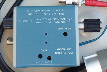
I use the 134 Amplifier with the P6019.
This little device 134 changes everything. Now, the P6019 will go down to 21 Hz fully linear, and from there to 12Hz @-3dB, and fully collapses below 7Hz. Also sensitivity is amazing. You can see signals of 1mA with very good resolution! Amazing is also to see the transformer based device work at such high frequency. I have to admit, my equipment can't hold up with it. So it's specified up to 50mHz? Yes, it sure looks like it, when I can display a square pulse of 30nSec. It really stresses my 80mHz scope to make this visible, and I must say about the 134 amp + P6019 combination, the pulse is displayed free of distortion. When I look at it directly on the scope, I see no difference with the current probe signal. Just a few nano seconds time delay.
So yes, they're only AC, but they go deeper down in frequency than any loudspeaker, any AC signal in an audio your amplifier or power supply.
 The 134 Amplifier is good thing. This is a high frequency amplifier with bandwidth up to 70mHz. It is made really nice, with an external power supply. So it is small and light weight. It features a clipping connector, which makes you can hook in up on any scope directly on the input. So to say, you add a current probe input to your scope that way. I am afraid to damage the scope like this, and I stick a cable-to-connector in there, so I can hook up a normal BNC cable on it. The output is 50 Ohms, so it will drive a cable without reflections. At the scope end, you need to use a 50Ohms termination, and then you can make indeed needle impulses visible, in the range of 30nSec, with the probe. For low frequency the 50 Ohms termination is not needed. The good part of the 134 is, there are many available, though prices are not any more a give away, as it was around 2018 when I bought mine. Yet they are affordable. So when it damages, you just buy another one, and sell the bad one for parts.
The power supply looks simple and crude, but it's not. It does not connect the ground of the 134 to the mains. Instead of that, this connection is done with two anti parallel diodes. So for electrical safety it's good, and yet it cuts the ground loop from the mains to the scope. So clever by Tektronix, and I never saw that before. I will remember this :)
When you are not so sure if DC is really what you "MUST" have, then consider the P6019 / 134 combination. I have two, in their original PLANO boxes, and they are great. Also they take almost not room on the bench, as I lay them underneath the scope. Perhaps I put two of them in an old TM500 module one day. Size seems to fit, and I can probably take AC power from the back of the TM500. I have an old impulse counter for the TM500. Still working, but perhaps I sacrafice it, to get the case.
DC Probes if you really need it.
Please note this about the Tektronix vintage DC probes. There was never build something like those any more, ever since, by no company. So the ones that are around and are GOOD, are little treasures. If they get defective, mostly that is a big problem. It can be a dead hall element, and that is end of the game. Replacement Hall Elements are impossible to find. It MAY be a loose wire, perhaps, but most likely it's the hall element itself. Also some probes are just more stabile than others. So if someone has a really good one for sale, don't argue very long about the price, that is one advise I would give. The other is, don't buy Ebay probes which are "probably good". I don't have to tell you how Ebay works. I was lucky myself though, buying a bunch of said to be defective probes in one buy. That's what they were. But from the parts I could assemble two very good ones. But they are very tiny inside, and when they are bad, sometimes it's hard to understand what the problem is.
A DC probe is made of an AC probe plus a Hall element for the DC and low frequency range. The first one, was the P6042, and it's still in interesting device, provided there is nothing wrong with it. The advantage today is, you use it as a separate unit on the bench, it simply has an output for your scope, and when you are done, you can put the probe inside, in a shaft. The disadvantage However, is, the amplifier is complicated, and they do get defective, and many parts to adjust. The probe itself is not so much different from the later family, but not compatible. Though the transformer assembly is comparable, you always have the probe + amplifier as a combination.
The Hall elements are quite variable. Some have negative offset, some have positive offset. The greater part of the offset is compensated inside the probe with hand selected resistors. So this means you cannot just replace the hall element inside a probe, by another. In that case you also need to re-adjust the balancing Inside. The final DC offset rest is adjusted to zero inside the amplifier itself.
When there is something defective with the probe it's normally the Hall Element itself, as these are the ones that get sold on Ebay. There no replacements around. Some real specialists operate the Hall Element out of a later 6302, but offset of 6302 Hall Elements is larger then P6042 Hall elements, so that is tricky. Also 6302 has two versions, of which you can only use the older version, with circular arranged pins, and not the one with a rectangular arranged pins. So consider a P6042 carefully. These seem to go for prices between 400 and 700 Euro depending on the quality. Myself I would rather pay more for a very nice one. If they studs at the back are cracked, it has been kicked around. Check the probe for cracks. If the probe screws look as if they have been taken out a few times with a non fitting screw driver, that is what it is So taken apart multiple times, but there are no serviceable parts inside, and they did not know how to use a screwdriver. Not the kind of service I am dreaming of.
Probe maintenance (That is for all probes).The magnetic core may not be touched with your fingers, and if so you must clean it with alcohol. Old cables can become stiff, until a point where it becomes very inconvenient, and you need to replace it. There are cables for sale on Ebay, good used ones, and sometimes NOS. I would not play with "any" cable, so you don't have one with the wrong capacitance or whatever. 50mHz is really a lot, and it would be a pity to compromise on that, just because of the wrong cable. The moving parts can be lubricated sparely with silicon oil. Do not use any other oil or grease, as that may crack the old plastics later. For service you can unscrew the BNC connectors, this is not a crimped connector.
The DC probes P6302 and A6302 do not differ so much from each other. The A is a later series. Inside can be a Hall Element assembly with rectangular connector or with a square connector. The square connector is the later version. I do not know how this relates to the A or P series. These were made to be used with a universal amplifier, or with a passive termination device. Logically with an amplifier sensitivity and bandwidth is a lot better. There are a few amplifier types around. Long ago, these were of course sold in a ratio of 1:1 probes + amplifiers. However, the probes are delicate, and today there simply too many amplifiers for sale. So the amplifiers are cheap and the probes are expensive. Unlike the P6042, when you have a problem with the amplifier for the later 6302 probes, you just buy another amplifier on Ebay at a low price. When the probe is good, it always works on a random, good amplifier. The amplifier AM503 is a unit which fits into a chassis. These mainframes can be bought with 1, 2, 3, 4 or 6 slots. So when it's a "current probe only" application, you can buy the TM501 chassis. Or, you may want to plug more units into the chassis, and you need the TM502, 503, etc. I prefer the TM504 because I can still carry it, and it has no fan. The next generation chassis is TM5000 series, which has a GPIB interface, 4cm higher size, heavier, they have a fan, and they're not fully compatible with TM500 modules. I expanded the 4 slot TM500 chassis with an 2 channel 80MHz scope, and the low distortion oscillator SG502. The scope can be externally triggered via the back panel with the oscillator, and by itself this set up is a great tool, for working on an amplifier, and it features a 50MHz current probe now. It's all I need :)
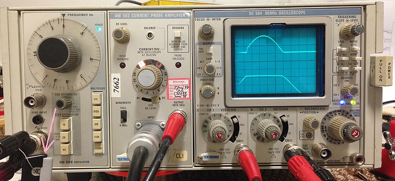
AM503 Amplifier with A6302 Probe. A very nice configuration inside a TM501 mainframe.
In the above measurement, on the left comes a sine wave from the signal generator. However, the output is shorted with a Schottky diode which clamps at 0.4V. If you look at the left bottom, you can see the A6203, with the Schottky diode inside. So the output can give only a negative voltage, or +0.4V DC. This is the lower curve, you can see the clamping. At this moment, the diode conducts, and the current is made visible by the current probe, which is the upper curve. The frequency is 500kHz, and you can see some ringing appears. The frequency of the ringing is like 10mHz or so, which is way within the bandwidth of the instruments here, so the ringing is in reality present, and not a side effect of the probe itself.
Measurements with this combination have the same quality as with the P6042. The next generation is the AM503 Amplifier with A6302 Probe. However, this probe is a probe only and cannot be used without amplifier. The idea is, that different series of instruments can work with the A6032 probe, by means of dedicated amplifiers, which have an A6032 input.
There is indeed the TM501 mainframe, with one slot only. You see this combinationTM501+AM502+A6203 quite often indeed. It is for people who want a working A6302 and no further requirements. Myself I choose for the TM504 mainframe with four slots, as this allows me to insert some other units, and also the TM504 is the largest one without a fan inside. You can simply plug TWO AM503 in there, and provided you have the probes, measure two channels. Well, I have those probes, and I plugged in also the two channel 80MHz scope in there. This scope is a bit tiny, and some parts of the functionality are tuned to the small size. But they did a great design job, and the inside parts are fantastic quality, full of gold contacts. It is a fine scope all together and nicely turns this TM504 into a versatile measurement tool. For in case I measure one channel only, I unplug one AM503, and insert the low distortion oscillator SG502. (Which so excellent low distortion it is amazing). Like that it is my favorite tool: SG502 oscillator+ AM503 amplifier with A6302 probe + SC504 Scope.
Here is the same setup but now at 50kHz. By compare it with the next picture, the AM503 amplifier's low noise quality can be see. In the above picture, the amplification if the AM503 is set to maximum, and the scope sensitivity had to be reduced to 100mV/Div.
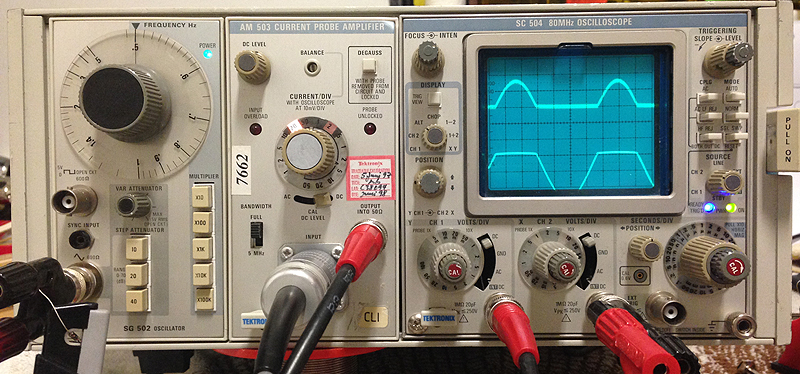
In this picture the vertical amplifier to the scope was set to highest sensitivity, 5mV/Div, and the AM503 amplifier set to 20x less amplification. So in the second picture, we are getting the amplification from the scope rather than from the AM503. It can be seen the lower picture is higher noise. So the conclusion is, best results come from setting the AM503 amplifier so maximum amplification, and reduce amplification.