Since 1993 Copyright Notice
Portrait of a Tube
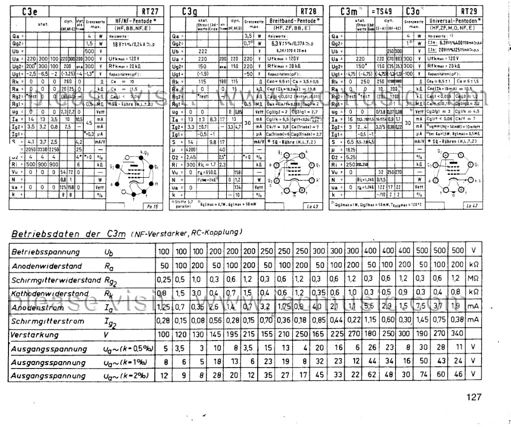
Description of the C3g and C3m tube
Perhaps the best small signal pentodes ever made
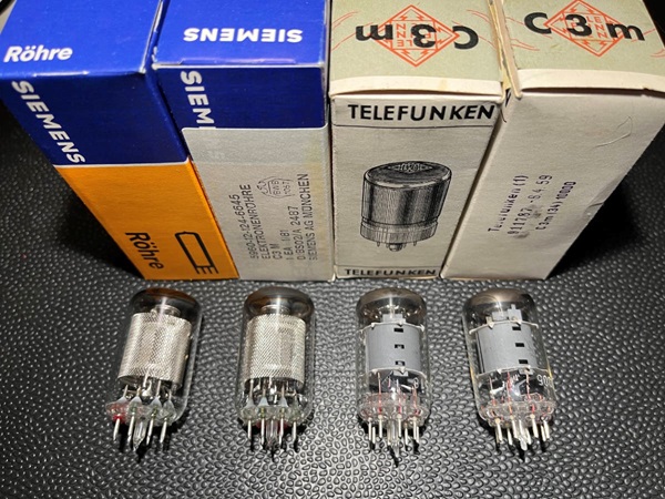
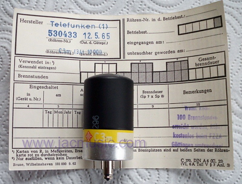
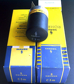
This article started off with a few pictures I made, about how nice a C3m tube looks at the inside. I removed the metal cap from a Siemens tube, because I wanted to know what is inside. Ever since, the content of this article has been growing. Today, even Yamamoto Soundcraft from Japan, equips their amplifiers with C3m tubes, without metal cap. Today you find such pictures everwhere. Just to honour myself, I was the one who started this hype, removing the caps. Sometimes there are questions or suggestions Siemens C3m and Telefunken C3m is the same. Probably they are NOT the same. Customers of me have removed the caps from Telefunken C3m, and at TFK a solid plate anode appeared. Whereas the Siemens I sell, will show a mesh anode when you remove the cap. Pictures are further down here.
CONTENTS
1. History of the C3g, C3m Series
2. Prices and quantities ever made
5. LOCTAL SOCKETS vs Octal Sockets
Admitted, in the steel can they are not glowing so nice. Believe me, once you feel these tubes get warm, you start to see them as tubes also. What is also nice, when you use them for the first time, there is the typical smell of warm paint, even after all those years.
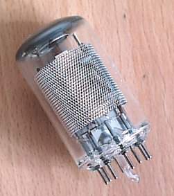
Siemens C3m inside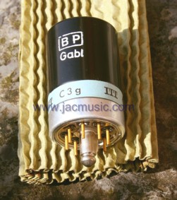
ITT C3g with cap
Every time, we have those people asking if not the TFK are made by Siemens. Well I guess at Ebay the re-branding mafia knows how this is done, but here you see see tubes from my own stock, which were sold to a customer in USA. He wanted to use them dismantled, and here you can clearly see the Telefunken look different inside. Thanks for the picture, Richard!
1. HISTORY of C3m, C3g SERIESI know not enough about this, to fill this part with best possible data. So please let me know if something interesting is missing. I will be glad to post it here!
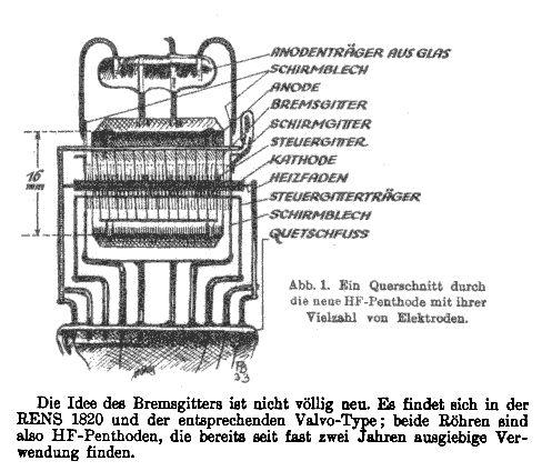
Later, as the French Alcatel and SEL merged, Alcatel played the standard game, transferring all competence to France, until nothing was left, and then dispose of the remains and old buildings. I believe the name rights ended up with Nokia. I suppose it didn't sound French enough to see any value in it. But... we have to say it: The Lorenz company in Esslingen was the designer of the C3m. The original purpose of this tube was described in an article in "Fernmeldetechnische Zeitschrift, July 1952" as a tube for audio and high frequency applications up to 500kHz. So this tube could be directly used to amplify audio signal, and also in carrier systems. (compare it with radio transmission, but via wire, so a modulated carrier signal). At that time the product was the V60 Telephone System by Lorenz. |
||||||||||||||||||||||||||||||||||||||||||||||||||||||||||||||||||||||||||||||||||||||||||||||||||||||||||||||||||||||||||||||||||||||||||||||||||||||||||||||||||||||||||||||||||||||||||||||||||||||||||||||||||||||||||||||||||||||||||||||||||||||||||||||||||||||||||||||||||||||||||||||||||||||||||||||||||||||||||||||||||||||||||||||||||||||||||||||||||||||||||||||||
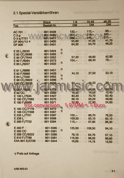
2. PRICESI have the original 1992 price list (not a copy). Here you can see C3g has cost 257DM for one. That is 130 Euro. The factory price for the standard 50pcs box was 4898 Euro. They still were used for maintenance. We have not reached this price level yet, but one day it will happen. All great tubes are now more expensive as when new made. Later, I received a copy of the Telefunken production quantities, sorted by the year. I have this data only for Telefunken,
|
||||||||||||||||||||||||||||||||||||||||||||||||||||||||||||||||||||||||||||||||||||||||||||||||||||||||||||||||||||||||||||||||||||||||||||||||||||||||||||||||||||||||||||||||||||||||||||||||||||||||||||||||||||||||||||||||||||||||||||||||||||||||||||||||||||||||||||||||||||||||||||||||||||||||||||||||||||||||||||||||||||||||||||||||||||||||||||||||||||||||||||||||
 C3m was developed in cooperation of the LORENZ company in Esslingen, Germany. Lorenz were the #1 producer of electronic systems which connects people with each other, making phone calls. Siemens was involved in that too. The Lorenz company later was named SEL Lorenz. They sold their telephone inter-connection systems worldwide, to the German Post, China, and many other countries. I visited that site, when I was a sales engineer for Hewlett Packard in 1989. The engineers worked in wooden barracks on a campus in Esslingen. Terrible buildings. Already by then, there offices looked like time capsules to me, But, they were "the" company for those systems. Just to imagine the business potential, though all we had to offer were red and green 3mm LEDs, which they used on their printed circuit boards. Still, when we could sell just ine LED in their printed circuit boards, oh boy... I had a big fish, and I am talking here about an LED which cost 6 cents in those days. Selling electron tubes was before my time, but just imagine what is was, to sell electron tubes to them, in the 1950s, when these where standard products! The tube cost 260DM in those days. Not 6 cents,... So you see, the Lorenz company was so huge, they could just tell the tube manufacturer what data they tubes should have.
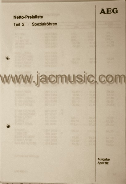
TELEFUNKEN |
Production start |
Production End |
Total Quantity ever made |
| C3g | 1967 Ulm | 1968 Ulm | 3500 |
| C3m | 1952 Berlin | 1974 Ulm | 332.000 |
Sometimes people ask me if it possible, Siemens tubes were made at Telefunken. Let me answer you like this. Some 30 years ago, in Switzerland was a stock C3g SIEMENS for sale, of more than 35.000 pcs. Also a German company offered them at the same time, by the thousands. (No it was not me, but I know this man personally). So no, I think Telefunken can not have made those for Siemens, as they only made 3500pcs ever themselves.
3. LOUD NOISES
Who can remember the 1980's with a long distance call from Europe to the USA?
Well, I can myself! In 1986, I worked for Hewlett Packard in Germany and phone call to California would cost 5$ per minute, so 300$ per hour. Which today is expensive but in 1986 that was REALLY expensive. And still the voice on the other end was not loud enough, there was a lot of analog noise on the line, and most of all one second delay. In today's money such a call would cost something like 900$ per hour. And yes, some of the marketing guys had such unavoidable things to do, they just called one hour or longer with their counterparts in California. Because of the bad connection, they started to speak very loud into the phone. That didn't help much against the low volume at the other end, but it did help to shut up other employees. I remember very well, how people in the Hewlett Packard Germany open office sounding so "important", by talking much too loud in English, indicating they were on an expensive long distance call. Some of the marketing people called several times a week, all the year through. That was another world as free calling via the internet. Why I write this? Well in those days, very probably those analog calls passed C3g, and C3m tubes from the German post :) I remember it like yesterday to me, but it was in my youth, it is long ago....
Anyway this is not what good signal transmission is about, but it was more touching the limits of what was possible with ocean cables. (Read the next part)
4. ABOUT ELECTRICAL NOISE
If there is one enemy of a long distance call, it's the combination of low signal and noise. But these two things come together, as if they are married. The reason for this is, a long distance telephone cable is a noise generator, and an attenuator at the same time. So after a certain length, the noise gets more and signal gets less. This limits the length of a telephone line, and simply amplifying the low signal at the receiving end, would also amplify the noise. That doesn't help much. So once noise is introduced at low signal, you can't get rid of it any more. Yet going into the cable with very high signal voltage is limited by practical things too. Even going in with hundreds of Volts AC signal, would give only noise at the other end.
If this is unclear to you, imagine the following. On a loud market place in the open, somebody shouts a message to you from 20 meters distance. You can understand it, regardless the noise. You could repeat the message, and shout it to the next person also on 20 meter distance. So you are a 'repeater', and with 20 repeaters, you can send a message over 400meter, regardless the high noise level. Without repeaters however, it would be hard to shout a message over 400 meter, but in a terrible market noise, you get a problem with what is called signal to noise ratio. So at 400 meters, suppose you would pick the signal up with a microphone and amplify it, the message would still be gone, it is drowning in noise, and you can't remove the noise any more.
So using repeaters is the only way to pass the message acoustically. Provided no repeater distorts (changes) the message of course. So what is important is no distortion, and repeat the signal before it gets lost in the noise. Without repeaters, this is simply NOT going to work.
You see, with a long distance voice transmission cable, all of this works just the same way. So the only solution is, to re-amplify the signal before it gets too noisy. It increases the maximum length of a cable, by putting in repeaters, by amplifying the signal before the signal-to-noise-ratio (SNR) gets really bad. Doing so, we can overcome distances from one continent to the other. Though practical situations are extremely difficult, and such projects are higher arts of project management. Imagine the weight of such a cable on a ship, or the trouble with tube repeaters in salt water, with a 4000 meters column of water pressure on a box full of electronics. Inaccessible for ever, somewhere between New York and Paris, on the ocean floor. You would want such electronics to WORK and not fail for silly reasons.
Going further back to the 1960's, this had to be done with tube equipment. Of course they tried to use as little repeaters as possible. The ideal repeater amplifier adds no noise, has no distortion, draws no current, is very small, needs no maintenance, and works for ever.
A partial solution you get from adding an auto transformer (Pupin coils) at certain distances, but there comes a moment where you need active amplification. So the engineers desired the 'ideal' tube. However, these ideal requirements do not go together well: High Amplification, low noise, long life, no distortion, small size, low filament power. As most of you know, a tube with more heater temperature will have better electrical performance, and more lifetime, but uses more power too. So the solution is a bit more complicated than you might think. Tubes that meet all of the requirements are masterpieces of design, and non-commercial since they are EXPENSIVE. The price of C3g was 295DM for one tube. So that's about 200$ for one tube. In those days you could buy a new car for 5000$. So a standard 50-Pack of those had the price of two new cars. You really need to imagine that. So obviously, cost was no issue with those, and that's logical since with those you could for instance work with a cable that had a bit higher loss, and add repeaters inside to compensate that. Imagine 1000km (1 Million meter) of cable can be made 20% lower cost, who cares if the tube that makes this possible costs 200$. This is the world of C3g, C3m, C3o. Sorry for this way of speaking, but I just wanted to bring my point, these tubes are not just any tubes.
 Today, I think most of the secrets of how to make C3-tubes are gone with the wind, but at least we can still buy those miracles of design art from new old stock. If the days come where we only can buy used ones, it's no problem too, since the end-of-life is clearly specified in the datasheets. So you can always tell if the tubes are still good. I found the Funke W19 tester very reliable in picking out used tubes with good lifetime in it.
These German post tubes were first designed in the heads of the amplifier engineers, that finally wanted to have something without compromise. The engineers just said, what must an ideal tube have, and then let the tube factories try to make it.
Here is what they came up with:
- Highest amplification
- Lowest low noise
- Lowest microphonics effects
- Higher lifetime than commercial tubes
- Stand-by possibility (very few tubes have that)
- Metal shielding
- If a pentode is triode connected, it must have curves like a real very good triode
- Fully complete datasheet, leaving NO DATA out.
- Optional: Individual series number on each tube
5. LOCTAL SOCKETS vs Octal Sockets
I try to keep the writing a little different with capital letters. So there is LOCTAL and Octal socket. These have the same number of pins, and same radius of the pins circle. But that is all. For the rest, everything is different.
LOCTAL tubes have a pressed tube bottom so it is one glass part, and the conductive material pins stick out directly. These pins are a mixture of metal and glass. Though with little glass, it behaves like a hard metal. Check this small video at 6C33 tubes, about such pins, breaking them off like glass. The glass content however make it possible, to weld those with glass. Moreover, peak current of such pins is limited by the tube socket only, whereas normal through-glass wires, are it is limited at 4 Ampere. The pins are melted into round glass balls of hard glass, called the “pearls” in tube production. So, pearls are bought as loose material, and 8 pieces are needed for a LOCTAL tube. These are pieces are glass welded into the soft glass base of the tube. This base was also a piece part supplied by glass factories, and they had 8 holes in it, for the pearls. After melting in, the pearls at the outside are flattened, but at the tube inside you can still see their original appearance. This base of the tube, later is welded on the glass bulb which is also soft glass.
Octal tubes are totally different. Electrically these have some disadvantages. These have 0. 4mm copper wires coming out of the tube, but copper does not seal vacuum proof with glass. To seal it anyway, in the middle is a nickel piece of wire welded on the copper wire, and the copper-nickel junction is treated with glass-like chemicals, which does something similar as soldering paste. Such wires can be welded only into special, more expensive glass, which is used for the tube stem only. The bulb is regular glass.
A third, process, combines the LOCTAL construction, as described above here, with a normal Octal base. Basically any Octal tube, when you see no stem inside, is one like this. The tube pins are3cm long, but now made of solderable material. This material is not the best there is, but for reasons of automatic production, it was used ever since on latest generation octal tubes. A remaining risk of very tiny vacuum leak stays always with such tubes, which leaks are not catastrophic, but it does use up the getter, which may end the life of a tube which could have been used longer otherwise. Just to put more emphasize to this, when a tube dealer can buy NOS 6SN7, so tube from the 1980’s or before, of such type, in SEALED boxes of 100 pcs, it is normal that 5% of the tube is bad, with white getter, because of vacuum leaks since 50 years. Once the boxes have been opened, such tubes can be easily recognized, and will be thrown away. Interestingly, we can say the remaining percentage of the tubes is fine. Yet we must keep in mind, most KT88 and EL34 are made like this today. From my personal experience, when I was buying new made tubes from Russia, around 2006 they had a MAJOR problem with this, and it becomes only visible as totally burned out tubes in the amplifier. This problem with new made Russian tubes was solved too slow, never admitted by the factory. For many years after it popped up randomly, damaging pairs of tubes, and users have to consider it bad luck. Though it was a plain manufacturing problem. It confirms my observation, the older tubes are, the better, and this continues all the way to the late 1930’s when quality was at it’s best.
With all the above writing in mind, where are we now with tubes which we can buy?
If they becomes very old, octal tubes, often develop some dirt inside the soldered octal base, resulting from the old solder flux. If stored not well, this can cause noise or leakage problems. Though this is rare. Bad solder joints may appear, which are not visible from the outside, and if sot his can not be repaired by tipping it with a solder iron quickly. If such a socket is removed, the copper wire inside is found covered with white-green oxide. However such problems are rare. If tubes with a glass stem inside, generic quality is normally very good.
LOCTAL Tubes are a quality grade above Octal. The hard glass construction, and lack of a solder process, prevents the problems of soldered Octal tubes. Moreover for inspection, you can directly SEE the position where the metal wire exits the glass. Moreover manufacturers most of the time clamp a metal ring around the tube, which is perfect for grounding, because with LOCTAL, the guide pin in the center is made of metal, and LOCTAL sockets have a 9th. connection for this. LOCTAL tubes do have one disadvantage, which arises nowadays with cheap Chinese sockets. The pins, if bend, will crack the glass along the pins. Of course, old time manufacturers of tube sockets were well aware, and prevented this. With Octal sockets, you rotate the tube in the socket, until you feel the right position and just push the tube in, even with force. When treating the tubes like a carrot, you may break off the qui de pin, but then you know it is your own mistake. With LOCTAL sockets, the guide pin is of metal. So, uncareful treatment would bend the pins rather, and for that reason the NOS sockets are made such, that the pins can ROTATE in the socket. There is no way to bend the pins. I would say, appr. 2mm movement is possible. Very UNFORTUNATELY, the Chinese socket manufacturers do not respect this requirement. They just modified an Octal socket into a LOCTAL, and that’s it. Selling those cheap, but users may damage their tubes with it. Be wise, when your LOCTAL tubes are low cost types, perhaps save on the cost of NOS LOCTAL sockets, but for expensive tubes, don’t do that! A good NOS loctal socket costs from 20…40 Euro, but they are worth it. If you plug or unplug a LOCTAL tube into a Chinese socket, it needs excessive force. It has this kind of “ouch” effect when the tube is pushed in. You just FEEL this is bad for the tube. That is because the pins itself are used to guide them inside. Reasons as explained above. A good NOS socket however has this nice, reliable feeling, and the tube goes in with a click. That is because the only thing you feel is the guide pin. The tube contacts itself slide in without force.
6. SPECIFICATIONS OF C3g, C3g-S, C3m
(LIFETIME LIMITS IN RED)
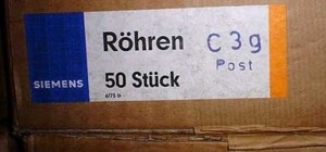
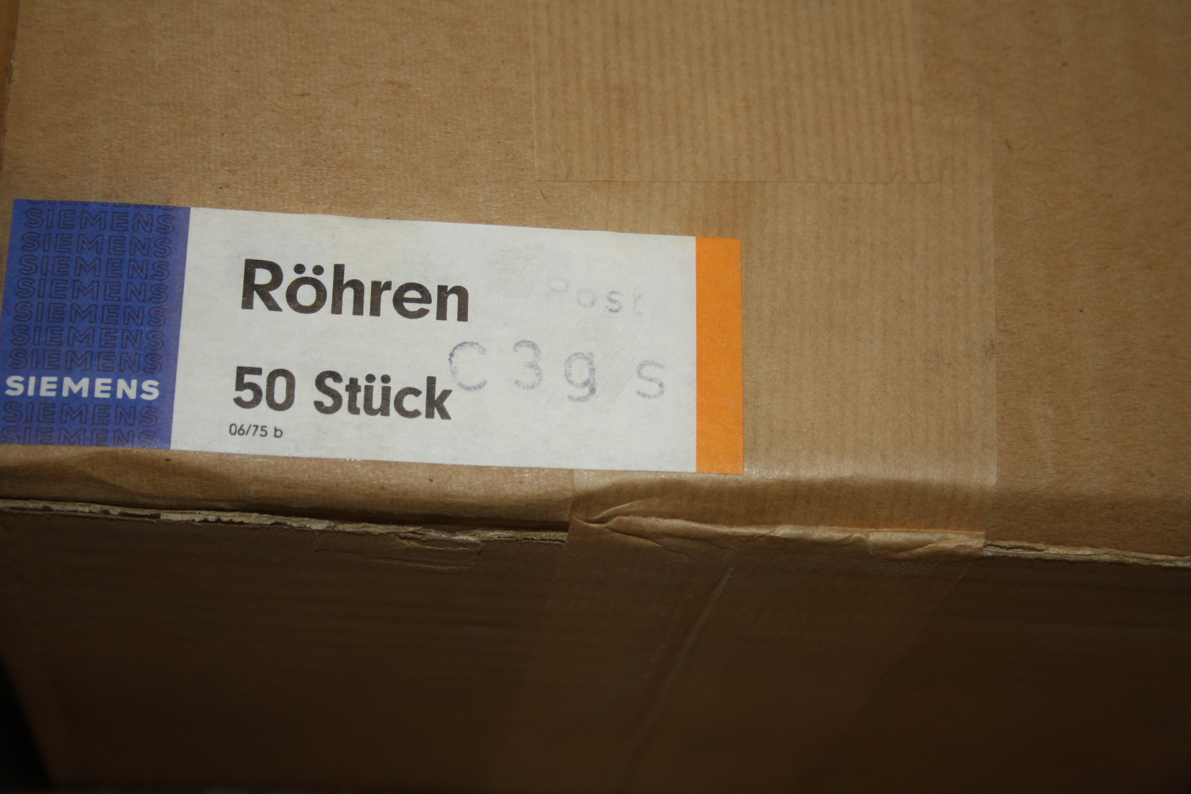
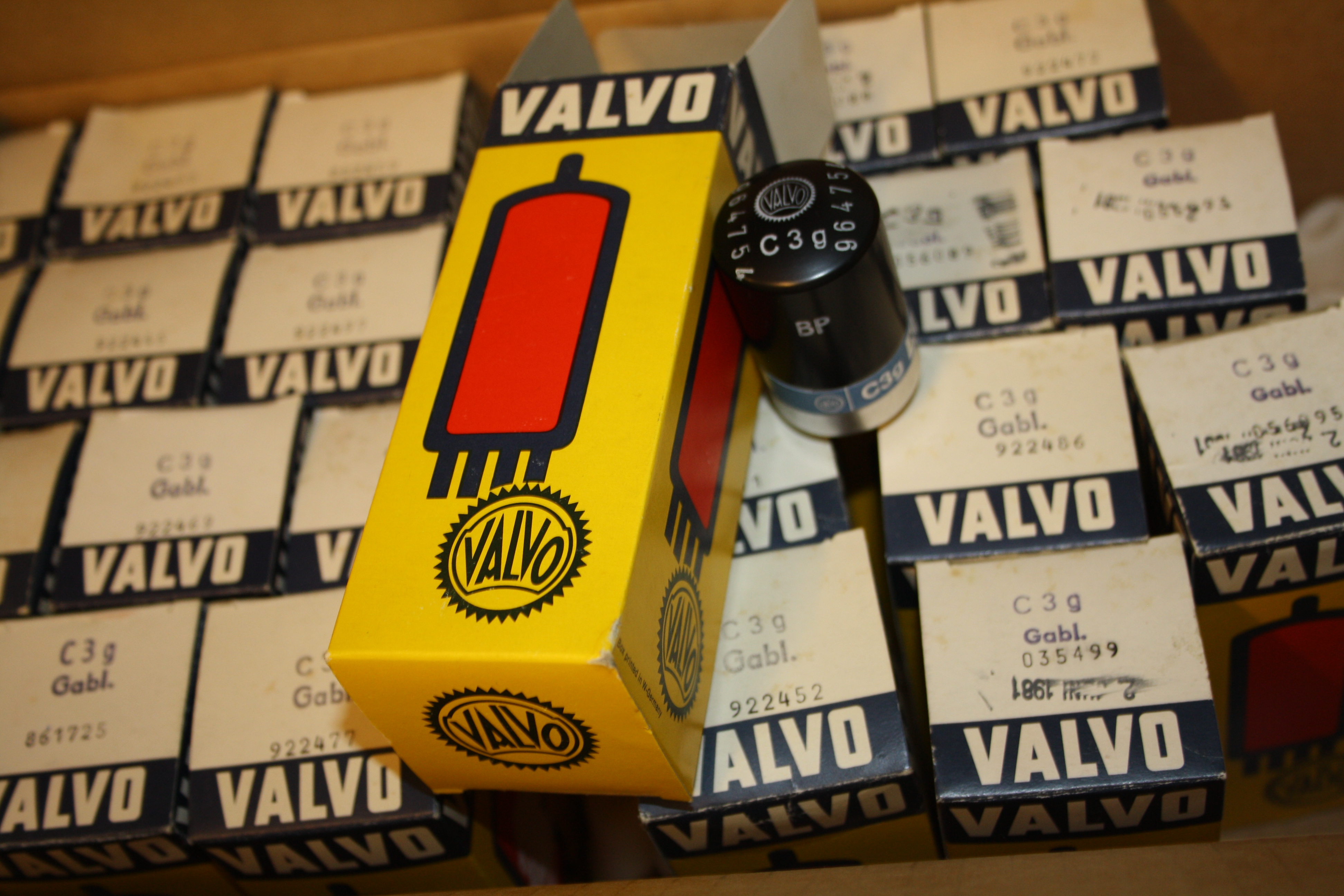
There is 'S' Version of the C3g that is said to me to be selected for higher minimum transconductance. I purchased those tubes from a retired Telefunken employee, who traced down big lots of C3g and C3m to where they were originally sold to, and actually found some. So I can say I have them from the first owner. However, I can find no information about the 'S', other than what he told me, and other than what is on the tubes and tube boxes. FOLLOWING I noted myself. The Telefunken and Siemens have the 'S' stamped on the boxes, but not on he tubes. This would logically mean, these are selected out of normal production. One exception are the VALVO. These have this designation' C3g/s' also in original white paint on the tubes itself too. At least this proves to me, this is something real, and not some special action done, for some customer. Also it must have been a big customer. I have such tubes from Siemens, TFK, and VALVO. Do not pay too much attention to this now, I will make accurate measurements later, when I have the AT1000 set up for C3g, and then I will see what is the selection is exactly about.
C3g-S unused |
C3g unused |
C3g after
|
C3m New |
C3m after
|
|||||||||||
Min
|
.
|
Max
|
Min
|
Typ |
Max
|
Min
|
Type
|
Max
|
Min
|
Type |
Max
|
Min
|
Type
|
Max
|
|
Ua |
.
|
220V
|
.
|
.
|
220V |
.
|
. |
220V
|
. |
.
|
220V |
.
|
. |
220V
|
. |
| Ug3 | .
|
0V
|
.
|
.
|
0V |
.
|
. |
0V
|
. |
.
|
0V |
.
|
. |
0V
|
. |
| Ug2 | .
|
150V
|
.
|
.
|
150V |
.
|
. |
150V
|
. |
.
|
155V |
.
|
. |
150V
|
. |
| Heater Volt | .
|
6.3V |
.
|
.
|
6.3V |
.
|
. |
|
. |
.
|
20V |
.
|
. |
. |
|
| Heater mA | 350
|
370 |
390
|
350
|
370 |
390
|
. |
.
|
. |
.
|
125 |
.
|
. |
. |
|
| Rk-h (ohms) | .
|
.
|
.
|
.
|
100Meg |
.
|
. |
.
|
. |
.
|
100Meg |
.
|
|||
| R Pin-to-Pin (ohms) | .
|
.
|
.
|
1000Meg |
.
|
. |
.
|
. |
.
|
1000Meg |
|||||
| Rk (ohms) | .
|
115
|
.
|
.
|
115 |
.
|
. |
115
|
. |
.
|
250 |
.
|
. |
115
|
. |
| Ia | .
|
.
|
.
|
10
|
13 |
16
|
8.3
|
.
|
. |
14.5
|
16 |
19
|
11.5
|
.
|
. |
Ig1,max (uA) |
.
|
.
|
.
|
.
|
. |
-0.5
|
. |
.
|
-1.0
|
.
|
. |
-0.5
|
. |
.
|
-1.0
|
| Ig2 | .
|
.
|
.
|
2.6
|
3.3 |
4.0
|
. |
.
|
. |
2 |
3 |
4
|
. |
.
|
. |
| Gm Pentode (mA/V) | 14,7
(*3) |
.
|
17
(*3) |
12
|
14 |
16.3
|
9.8
|
.
|
. |
5.5
|
6.4 |
7.8
|
4.5
|
.
|
. |
Gm Triode (mA/V |
.
|
.
|
.
|
.
|
17 |
.
|
. |
.
|
. |
.
|
. |
.
|
. |
||
Ri (Ohms) |
.
|
.
|
.
|
.
|
2k3 |
.
|
. |
.
|
. |
.
|
. |
.
|
|||
Ri (kOhms) |
.
|
.
|
.
|
.
|
300 |
.
|
. |
.
|
. |
.
|
250 |
.
|
. |
.
|
. |
Gain Pentode connected *2 |
.
|
.
|
.
|
.
|
4200 (in theory) |
.
|
. |
.
|
. |
1625 (in theory) |
. |
||||
Gain Triode connected *1 |
.
|
.
|
.
|
.
|
41 |
.
|
. |
.
|
. |
.
|
19 |
.
|
. |
.
|
. |
| *1 From TFK datasheet | .
|
.
|
.
|
.
|
. |
.
|
. |
.
|
. |
.
|
. |
.
|
. |
.
|
. |
| *2 Tested with AT1000 | |||||||||||||||
| *3 My personal observations | .
|
.
|
.
|
.
|
. |
.
|
. |
.
|
. |
.
|
. |
.
|
. |
.
|
. |
C3g, C3m, C3o, what's the difference?
C3g was made after C3m, and C3g has a frame grid and gold pins. Frame grids generally give better quality tubes, though it must be said that the quality of C3m is just as superb, and I make the statement here for C3g and C3m, that there is no better tube available of the same kind. If you think I am wrong, email me with facts from a datasheet, and if you find a better tube, I will add it here.
Generally with C3m and C3g it can be said they have the gain of a pentode, and distortion same as only the finest triodes like E80CC. However, C3m will give that low distortion at a gain of 78. (and E80CC only at a gain of 25).
A gain of 78 It means you can drive a 300B with just one C3m, and you have less than 1V input sensitivity. In a few words, this explains why these tubes are so great for HiFi purposes. For applications like pre-amp tubes, or driver tubes for 45 or 2A3 the C3g can be used as well.
They show their extreme low distortion only as pentodes. They can be used triode connected, but then gain comes down a lot, and the distortion increases to a level just below triodes like 6SN7.
Heater voltage
C3m was often used in telephone repeaters, that are remote units, somewhere far away, and the heaters of those are higher voltage and lower current. This was also done by Western Electric for Telephone tubes.
C3o is a C3m with 6.3V filament. However, C3o is exceptionally rare as NOS tube. But we have some 20...30 pcs on stock.
C3g |
C3o |
C3m |
|
Filament |
6,3V | 6,3V | 20V |
| Pins | Gold | Normal | Normal |
| Grid | Frame | Normal | Normal |
7. The 'S' Version C3g-S
C3g-S is a hidden treasure. They are EXTREMELY rare. I mean the real ones, not the fakes. Oh yes.... the 'S' is faked, but that can be seen so EASILY by tube testing. Please read more about 'fake' testing here, because some sellers do so with the U-trace.
So far, I was not able to find the factory specifications for this, but one day, I hope 'coincidence' is going to help us out here. I have seen the original test tools for C3g and C3g-S selection myself, in Ulm. This was a dedicated plug in unit, for a universal test bench. The bench was like 1 Meter wide, and the operator had to add plug-in units to it, for C3g or C3m, C3o. etc. The unit had lots of knobs and instruments on it. The tubes were tested one by one, by hand, and many settings had to be made, before all parameters could be tested.
About the S-Version, the following I know for sure, because I was told so first hand by an Ex Telefunken Employee, who was at that time involved in this. The S-Version is selected for a SEVERAL things at THE SAME TIME. One of those the Transconductance exceeds the datasheet value by a minimum percentage. From my personal measurements, transconductance is from 105%...to 110% at normal (so 13mA) plate current. However, make sure, you don't get fooled by auction website sellers, shipping you normal tubes with an 'S' printed on them.
![]() WARNING!
WARNING!
WARNING ABOUT FAKE TESTING, AS I HAVE SEEN IT ON AN AUCTION PLATFORM.
This fake testing trick as as simple as it it easy. Don't be fooled! They begin with showing you official, printed test information.
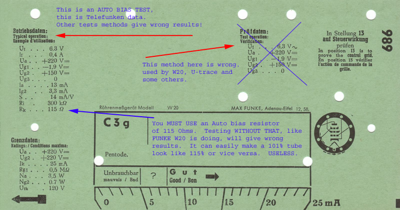
This is hard to explain in just a few lines. Saying you have tubes with 105% Gm, testing this way, means only you have tubes with 105% Gm tested THIS way, and NOT the Telefunken way! This is really not a good was to test. For this, you need to understand the difference between auto bias testing, and fixed bias testing. If you would think now: Is there a difference? Then don't worry, many think so. But yes, it makes a BIG difference. For those tubes, where it DOES matter, you better look twice who sells you what, because this is not without a reason. There are some (very few) tubes which have an official datasheet with AUTO BIAS specifications only. Such tubes are always high quality tubes, like C3g, C3m, C3o, or their little sister D3a.
Why Auto Bias testing is the PROFESSIONAL way. There is a great l misunderstanding, that auto bias testing is not telling us enough, because the tubes would "auto bias" anyway. We want to see the differences of course, with fixed grid voltage, right? Well, this is WRONG. Let me explain why. First, a big hint for this is, only exceptional quality tubes have auto bias circuits published with end-of-life data. But was does Auto bias tell us? if the tube reaches within very close tolerance, it's predicted working point, what does this require for the tube? So lets's say we have a 13mA tube, we auto bias it and it pulls exactly 13mA. What can we say now? Well it seems to be able to draw this current in the first place. If there is any problem with that, auto bias can solve some of it, but not everything. So you will see some loss of plate current. If small, that means at least the gain is still good, because there IS a problem, but we can see auto bias is fixing most of it. Next thing we see, is transconductance is measured at it's normal current, as it should. So the tube is working at full current, gain is good, because otherwise auto bias can not work. Quite a lot of data actually. Roughly, we can say, if the auto bias current is 10...15% too low, the tube is not good any more.
Unofficially. When you test in auto bias mode, you will see the tube finds 90% of its normal value within short time after the cathode begins to work, and the remaining 10% doesn't take long either. That is because the tube for DC, is in a feedback loop, using it's own gain. So as soon as gain is already partially present, auto bias works, then the set point is quickly achieved, even the tube is not yet fully warm. With USED tubes however this takes longer. Simply because gain has dropped. When you test with fixed grid voltage, this interesting mechanism you will not have. Tubes take a lot longer to be ready to test, and the warm up time gives no good hint.
HOW TO TEST Gm? There is only one way: This has to be done at 100% plate current. There no other way, not for these tubes here, and not for any other tube. And yes, all new made testers (100% of them!) ignore this knowledge, and I would say ignorance that is the best word for this indeed.
The tube tester W20 (Card from above...) makes the same mistake, but at least they have corrected the 'good begins at' level to one which can be expected with fixed bias. So, a 13mA tube is considered to be 'good' above 8mA. Whereas the German post, who designed those tubes, never said so, and also never said this is the right way to test them. They are not doing it wrong actually, just not by Post specifications.
A VALID TRANSCONDUCTANCE MEASUREMENT IS ONLY AT 100% PLATE CURRENT |
|---|
This brings us back to auto bias testing, because in auto bias, a good tube is close or at 100% plate current by definition. (and if not, it is bad). Any Gm test at a random plate current, such as you would get with fixed bias, is indeed just something random, and little more than that.
Now for the S-Version. Very simple: These must have >105% Gm at 100% plate current. They must be like this, and nothing else.
A tube which has 105% Gm, but needs 115% plate current for this, is just a normal tube. If these are marked 'S-Version' it cannot be true.
CONCLUSION: You need Gm as a minimum 105% at 13mA.
So at 13mA, any tubes with just Gm >105% and the plate current is accordingly lower, these are normally good tubes, but no S-Version. So when Gm is 5% higher and anode current is 5% lower, that a normally good standard version tube. The Emission Factor of this tube is 100%,.
As a rule of thumb, the average of Gm performance and Ia performance must be 100% for a new tube. So Gm = 105% and Ia =95%. Average is 100%, this is a new tube. Or, when Gm=105% and Ia=80%, this is an average of 93%. This is not a BAD tube, but under the assumption this is NOS, this is definitely not an S-Version. Or if we are SURE it is an S-Version, like picked from original equipment, then it must be a used tube.
For NOS tubes, when Gm is at 105% and plate current is 20% lower like 10 or 11mA, this can NEVER be an S-Version tube. When it's printed on the tube boxes and tubes itself, do not be mislead by this, because S-Versions can easily be verified by correct measurements.
Also read (and try...) the below experiment, it will open your eyes.
Some examples:
Gm = 105%, Ia =12.4mA (95%) NOS condition Regular Version
Gm = 95%, Ia =105%: NOS condition Regular Version
Gm = 105%, Ia =13mA (100%): NOS condition C3g-S
Gm = 110%, Ia =13mA (100%): NOS condition C3g-S
Gm = 105%, Ia =16mA (100%): NOS condition C3g-S
Gm = 95%, Ia =105%: NOS condition Regular Version
Gm = 105%, Ia =11mA. NOS condition Regular Version, or USED tube S- Version
Gm = 105%, Ia =10mA. END OF LIFETIME tube, because <10mA is a bad tube.
1st. advise. If the above is not fully clear that is because this is indeed not easy to explain. But, I have tried, and best is, just read it a few l times, until a light begins to shine. Also do the next experiment if you have the equipment:
Experiment: Take a C3g, which is reasonably good, but you sacrifice it for this experiment. Suppose Gm=95% and Ia =12.5mA. So slightly used. Now knock the tube on the table. Such that you deform the inner structure, but not damage the tube totally. Now re-test it, and you will see, Gm=105% and Ia= 11mA. If there was no change, you didn't hit the tube hard enough. You can also try this with an old EL34, because these react to this much more sensitive than C3g. It is crazy, and you wouldn't want to know how many EL34 or C3g have been 'improved' this way to sell it on an auction site. This will easily fool a fixed bias test, but it can never fool an auto bias test.
2nd. advise. Any 'S' versions are rare and expensive. Makes sure, Gm is tested ONLY 100% plate current. Let nobody fool you.
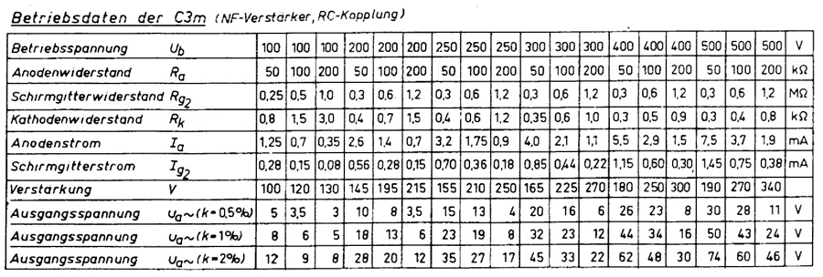
Build a pentode pre-amplifier stage with C3m
Take a normal Cathode resistor stage, and use this table. More details in the official Telefunken datasheet
8. Applications:
- Inside active microphones.
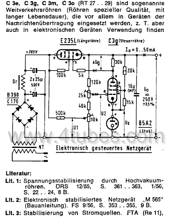
- Very Stabile instruments, with DC coupling, like stabilized power supply.
- Low microphonics applications. C3g mainly (frame grid)
- triode connected, or pentode connected
- driver or preamplifier stages. C3m for high gain.
- phono amplifiers. Searching for the holy grail? The C3g or C3m! Finally.. LOW NOISE!
From the fact they both C3g and C3m exist, you can see they both have their own justification. So don't ask which one is 'better'. Same as with ECC81, 82, 83, there is C3g and C3m.
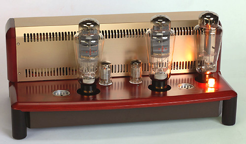
Yamamoto A09 amplifier with C3m (Metal cap removed by Yamamoto)
Some small note about low distortion.
In pentode mode, C3m has distortion figures compared with E80CC, but at much higher gain. (at 5Vrms out, E80CC has, with bypassed cathode, a gain of 25 and 0,16% THD. C3m has a gain of 78 and 0,12% THD).
![]()
More datasheets. can be found in the tech corner of www.4tubes.com (See also the top menu)
9. Photo Gallery
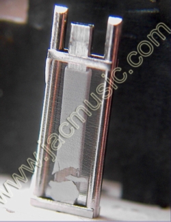
Let me bring to your attention, the C3g at it's introduction in 1952 was the fist Frame grid tube, and it was not available commercially. In short, a frame grid means the grid wire is not self supporting, but is wound around a hard metal frame. Like this, they could use wire which is so exceptionally thin, as it was never possible before. You cannot see this wire with the bare eye. This is quite strange to observe, when you take a frame grid tube apart. The grid wire is there of course, and you can 'see' there is something there, that you can look through, but you cannot see what that is. As if there is a gold colored, transparent layer, that you can see through. Things looks a bit 'unsharp' when you look though. Like the low resolution picture below. It is just like this when you look at a frame grid wit the bare eye. Then, if you click the picture it gets enlarged, and you can see the wires. This technology is more expensive, and was used for very few tube types, perhaps 100 only. Given the 10's of thousands other tube types ever made, this is not much.
Read here about frame grid tubes.
NOTE that in the 1980's when tubes were obsoleted, there was a lifetime-buy option by Siemens for the German post. It stretched over a few years. It is from this period that BIG lots of tubes were made, and just stored for later service of old hardware. Because of the high manufacturing numbers, these were very good quality. Popular tubes were C3g, C3m, and also Siemens ECC801S of remarkable good quality. Probably many other tubes as well, it's just these three Types I ran across myself. Something similar happened in the USA, and from that period many very good 6922, 5687, 12AT7 and 5751 are around. These are those tubes with a barcode label on them.
Then, the whole hardware developed so quickly after the digital multiplexing was used, and analog repeaters were taken out of service everywhere sooner than expected. And so, a six digit number of those tubes were stored and never used. Through the years these were sold, and it seems the German government stocks of C3g and C3m have dried up since 2005 or so. However, these tubes are always somewhere, and find the path to their end user.
Check for a 16 pages (!!) datasheet at our website / under Techcorner
I guess they came up with some more nasty things, that the tube manufacturers all had to comply with. Just look at how nice the triode connected curves are. These curves are so linear, I think there are very few triodes excising with such nice curves!
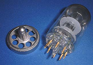
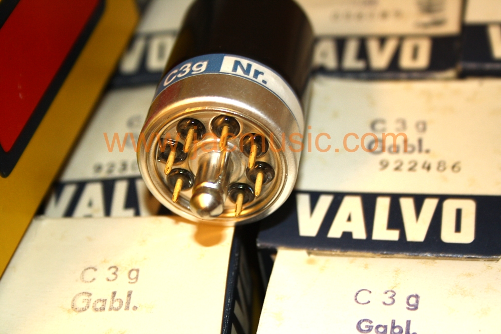
What to do, if you don't like the metal cap?
You can take off the metal housing, and inside is a very nice glass tube!
| C3m inside |
 C3g with cap |
C3g Inside.
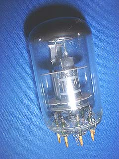 Look at the two round plates above the pins. The lowest is a metal shield (outside connected) for lower hum. The other is the mica. The anodes are open from the sides. This open construction is the best for finest linearity. It allowed plate distance adjustments after the tube was assembled. This noncommercial construction was used already in DHT post tubes from the 1930's
Zirconium + Barium Getter
We are lucky to have only the C3g and C3m version with the additional zirconium getter. So that is additional to the Barium getter ring (or plate).
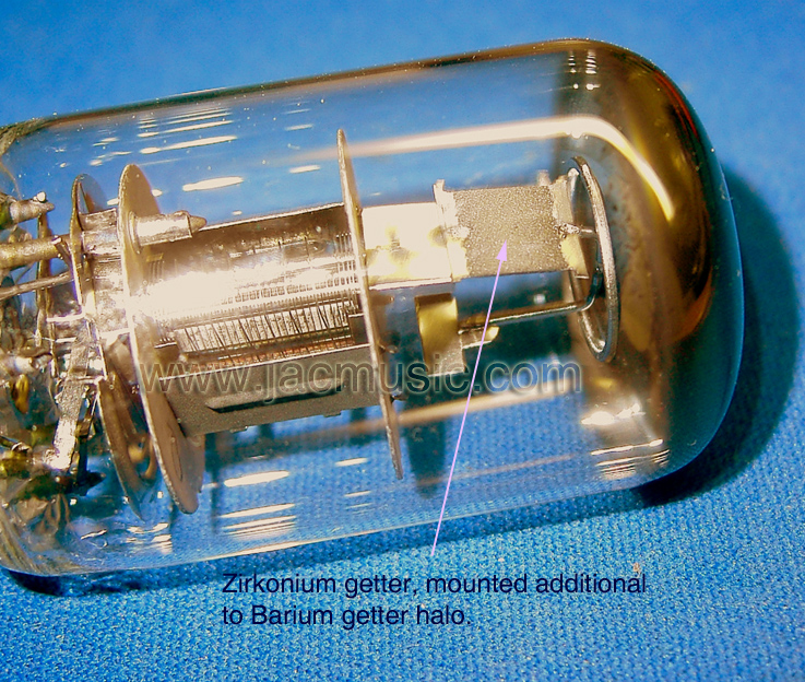 A Zirconium getter is expensive and it works like this: A Barium getter has most of its function during the short moment (a few seconds) that it is flashed during production, so when it is in the tube in the form of a cloud, while being transferred out of the getter halo, and condensing on the tube glass. This cloud, at the moment it exists inside the tube, absorbs (at that short moment) almost anything whatsoever. Then, after it will be condensed on the glass, the Barium getter is only conditional active. Like during great heat such as with KT88 tubes. However, little tubes like C3g cannot really use the getter anymore after activation. Of course there are some remaining functions left, amongst which is dust catching (yes!) but maintaining extremely high vacuum is not done. Here is where the Zirconium getter comes in. These need no flashing. They start to absorb gasses, whenever they have a sufficient temperature, and all you need to do is, mount it at a warm place. So really top class tubes have both getters. These tubes used to cost 295 DM when new, I have seen an original price list myself.
Zirconium getters can have various appearance. Some can be small square plates as you see here. With other tubes like EL503 they are hidden inside the plates. Tubes like 845 have Zirconium absorbed inside the graphite. With the 845 the Barium flash you see, is only used for initial vacuum during production. Maintenance of the vacuum is done by the Zirconium getter.
A Zirconium getter is expensive and it works like this: A Barium getter has most of its function during the short moment (a few seconds) that it is flashed during production, so when it is in the tube in the form of a cloud, while being transferred out of the getter halo, and condensing on the tube glass. This cloud, at the moment it exists inside the tube, absorbs (at that short moment) almost anything whatsoever. Then, after it will be condensed on the glass, the Barium getter is only conditional active. Like during great heat such as with KT88 tubes. However, little tubes like C3g cannot really use the getter anymore after activation. Of course there are some remaining functions left, amongst which is dust catching (yes!) but maintaining extremely high vacuum is not done. Here is where the Zirconium getter comes in. These need no flashing. They start to absorb gasses, whenever they have a sufficient temperature, and all you need to do is, mount it at a warm place. So really top class tubes have both getters. These tubes used to cost 295 DM when new, I have seen an original price list myself.
Zirconium getters can have various appearance. Some can be small square plates as you see here. With other tubes like EL503 they are hidden inside the plates. Tubes like 845 have Zirconium absorbed inside the graphite. With the 845 the Barium flash you see, is only used for initial vacuum during production. Maintenance of the vacuum is done by the Zirconium getter.
Cap Removal
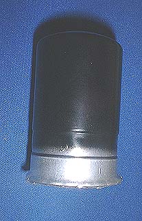 It is really a matter of taste of you want to remove the cap or not. The optical advantage is beautiful. For myself, knowing what is inside, for me it is a tube as well also with the cap in place. Make good note, what the cap is intended for: It is an electrical shield for the tube, and the cap is electrically connected to the metal guide pin, in the center. So via the tube socket you can ground the cap. This is definitely a great advantage in case of very low signal applications. For a driver or headphone, removing the cap for optical reasons is sure nice. You can lift off the edges of the cap relatively easy, it is aluminum, and not aggressively attached or kitted. Also the tube glass will not break easily, because the location is the tube base, and this is pretty thick material. Yet, it is possible to break the glass still when you do not patiently peel the cap away.
After removing the cap, the part with the guide pin falls of, and I would recommend to glue this back on. Put two components glue on the sides. Important: Do not fill glue in the center adjustment hole. That will eventually break the glass pipe in the middle. Note that one pin hole is square, and is used for positioning. Also you can now still use the guide pin to ground this part, and one way or another that is simply good, because the ground plane comes now closest possible to the hum sensitive grid.
Note: Hum is greatly reduced by using a low driver impedance. Also, when working at very low signal level, be ware that with all tubes, the grid noise, generated by the tube itself, is actually attenuated (better call it loaded), when using a very low impedance driver circuit. So the noise free signal from the driver and the noise from the tube, will not simply add up, but only one of the two will win. And that will be the driver signal, when it is low impedance. This has nothing to do with the C3g or C3m itself, but since C3g, C3m can be used in pre amplifiers, or even phono amplifiers, I think it is meaningful to mention this here still.
C3g C3m Photo Gallery and ORDER NUMBERS
These are pictures of my own tubes, THESE are the ones you would be send, in case you buy some.
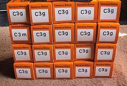
C3g Siemens
Order Nr: 114-146-50
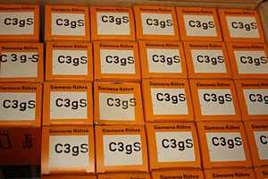
C3g-S Siemens. From 1975
Order Nr: 114-147-63
C3g-S Valvo
Order Nr: 114-151-93
C3g Valvo
Order Nr: 114-150-29
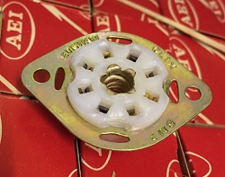
Ediswan vintage TEFLON socket for C3g (we found those with it)
Order Number: 398-803-99
Though not visible on the picture, it DOES have an electrical contact to the guide pin.
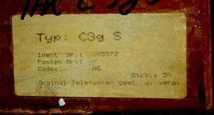
C3g-S Telefunken, with Lot Number 005572
C3g-S Telefunken Sorry NOT Available any more.
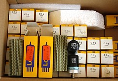
C3g Lorenz. Some boxes
have Date code 1978.
Order Nr: 114-144-48
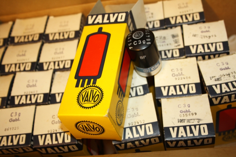
C3m Older Boxes