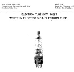
Portrait of a Tube
Western Electric 310A
 These tubes were send to me for repair, complaint was the top caps are loose, and the tubes are noisy.
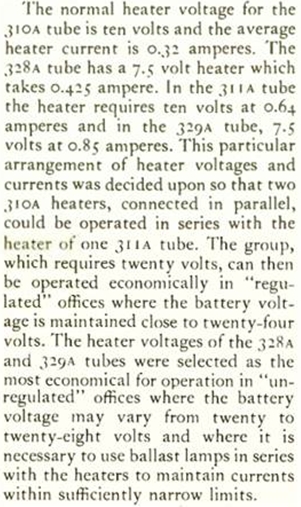 The heater of the 310A is 10 Volts. This has following logic: Such tubes were intended for field applications, running off 12V lead acid battery systems. So the heater still keeps on working even if the battery is getting low, such as 10V or lower. This was important for the application. When the battery is charged, you have 13.8 Volts, so that reduces lifetime of the tubes a lot. As you can see, operation at a "low" battery comes first with 10V tubes. For long life, you need to use the 12.6V tubes. I have this informatiom from an unofficial military information sheet about another 10V tube. Just as 5V tubes were good devices to run from a 6.3V battery which is getting a bit "low", 10V tubes could be run from 12.6V batteries the same way.
Similar information comes from O.J.Macnally from Bell Telephone Laboratories, where it is said two 310A in series would giev 20V and this can be run from a 24V battery with a ballast tube in series. (A ballast tube is a constant current user, this stabilizes the current trough the heater and in that way also the voltage across the heater).
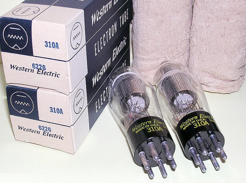 The 310A is a made for Audio applications, and for RF applications as well, like oscillators or modulators. It has a top cap, but other as you may think, this is no plate cap. This is a grid cap, ensuring low capacitance. For HiFi, the grid cap is not under high voltage, so it is not a dangerous connection. The cathode is formed around a ceramic pipe, which beautiful technology I remember from Telefunken 1930's Radio tubes of the RENS series. It heats up the cathode very slow, but it gives a nicer build cathode. I have no broken WE310 A to open it, but it seems as if I see a gold grid at the inside.
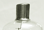 So I thought, here we go and repair those plate caps quickly. Amazingly the grid caps were loose, but they did not want to come off easily. The whole cap was filled up inside with glue. I have no pictures of this, since I repaired the caps already, BEFORE I found the terrible mess with the tubes base, and decided to post the pictures here. Filling up the whole cap is wrong, since that can break the glass pearl at the top. This would happen if there would be permanent force on the pearl.
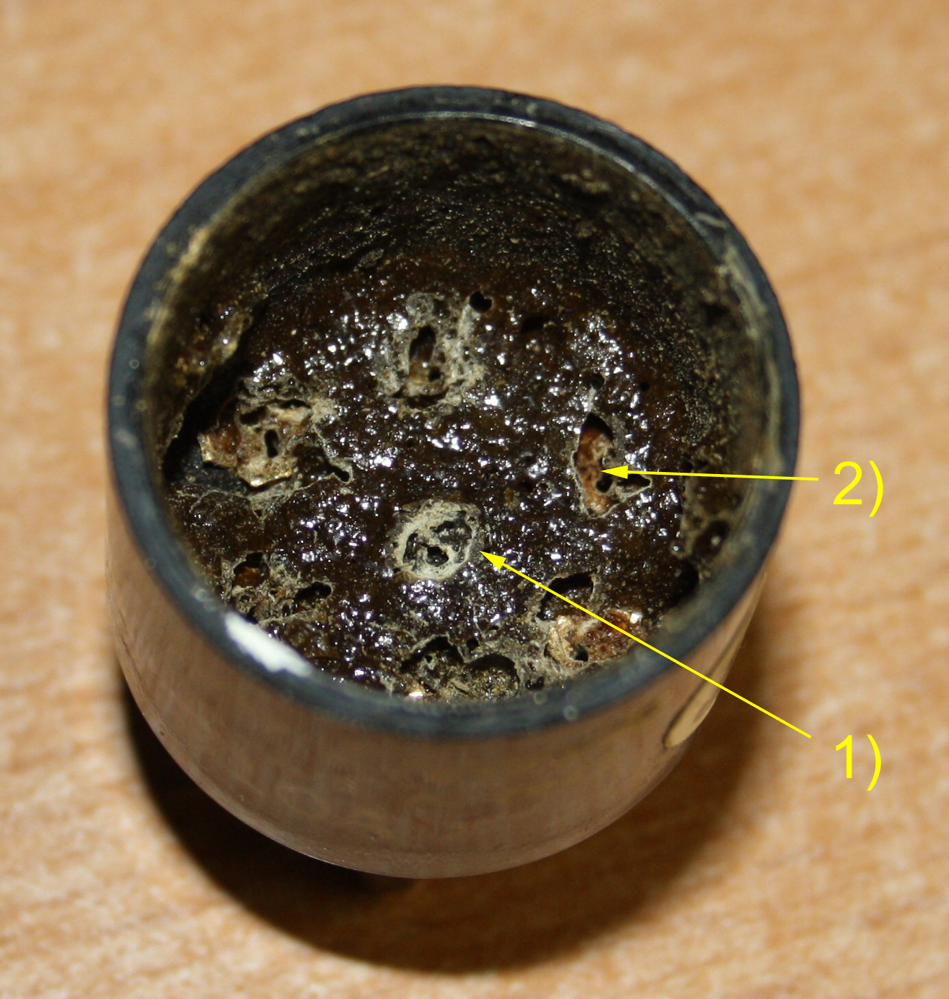 Then the next surprise came after I was done with the grid caps. One of the tubes had the base wiggling a little bit. It was not really loose, so an ideal candidate for the special tube glue we make ourself, and we re sell also. The tube was glued and dried. Strangely it still wiggled a little bit. So we move it until a new opening occurs, to let a second charge of glue drip in, and this always cures it. Not here, even a third glue attempt helped not at all. So I decided to take off the base and see why the h... caused this, because it is not normal. Out came a mega surprise, I have never seen such a thing before. This is WESTERN ELECTRIC? Yes it is! What a bad job, what a mess! Even the Chinese would be ashamed of them self for this, but hey... we talk about a USA made, Western Electric NOS tube here. Click on the left picture. What you see here, all glue had dripped inside the base, causing this thing we absolutely do not want. This cement is not a very good isolator. It makes noise when you make a connection from the plate to the grid, with cement. If that happens, we talk about having a drop or some smear inside. Sometimes a noisy tube can be repaired by removing that cement residue. But what do we see here.... Not some smeared drop, but we see here a complete BATH of cement, connecting all electrodes together with this (noisy) organic mass, called tube base cement. So now after 60 years, we're going to fix this mess.
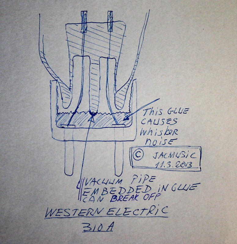 This really ends the myth for me, of Western Electric being the greatest tubes on earth. In the middle of this drawing you see the glass pipe though which the tube vacuum was evacuated. It is also this Nr1. in the above picture The glass pipe is damaged very very easily, meaning you loose the vacuum. What do we see here, it was simply cemented inside the tube base. So the glass pipe was resting on a hardened layer of tube cement. The tube bulb was wiggling on that pipe, while it was held by the connection wires only. It did not become that way, It was MADE that way.
Western Electric used a cement from the Borden Company, which was mixed with alcohol and some green malachite mineral before application. The completed tube was then oven-baked (175°C) until the green compound turned brown (which was the sole purpose of the malachite addition).
In a practical situation this cement dripping problem may have these causes. I know this from our work at the Emissionlabs tube factory.
- Too much alcohol (solvent) added.
- Old, prepared cement was re used, instead of disposing it after the maximum use process time a four hours.
- Oven temperature set too high.
All cement inside was burned dark brown. So we talk about cause #3. What I cannot explain is, However, why the stem was filled with cement too. This is totally wrong. This indicates the tube was put upside down in the oven. Such mistakes are totally none-Western Electricfor mr, but it was made here, and I pictured it. Moreover this was not a licenced tube, it was an original WE tube. Conclusion: We all make mistakes, don't we.
I received some critical remarks by email for saying this, but it's just reality, and it's better saying it here, than keep up some myth. Same applies for the top caps, which get loose quickly.
At Emission Labs, we have had enough experience with that base mounting glue. Today we use modern compounds. This replaces this cement in a better way, and the base doesn't break off.
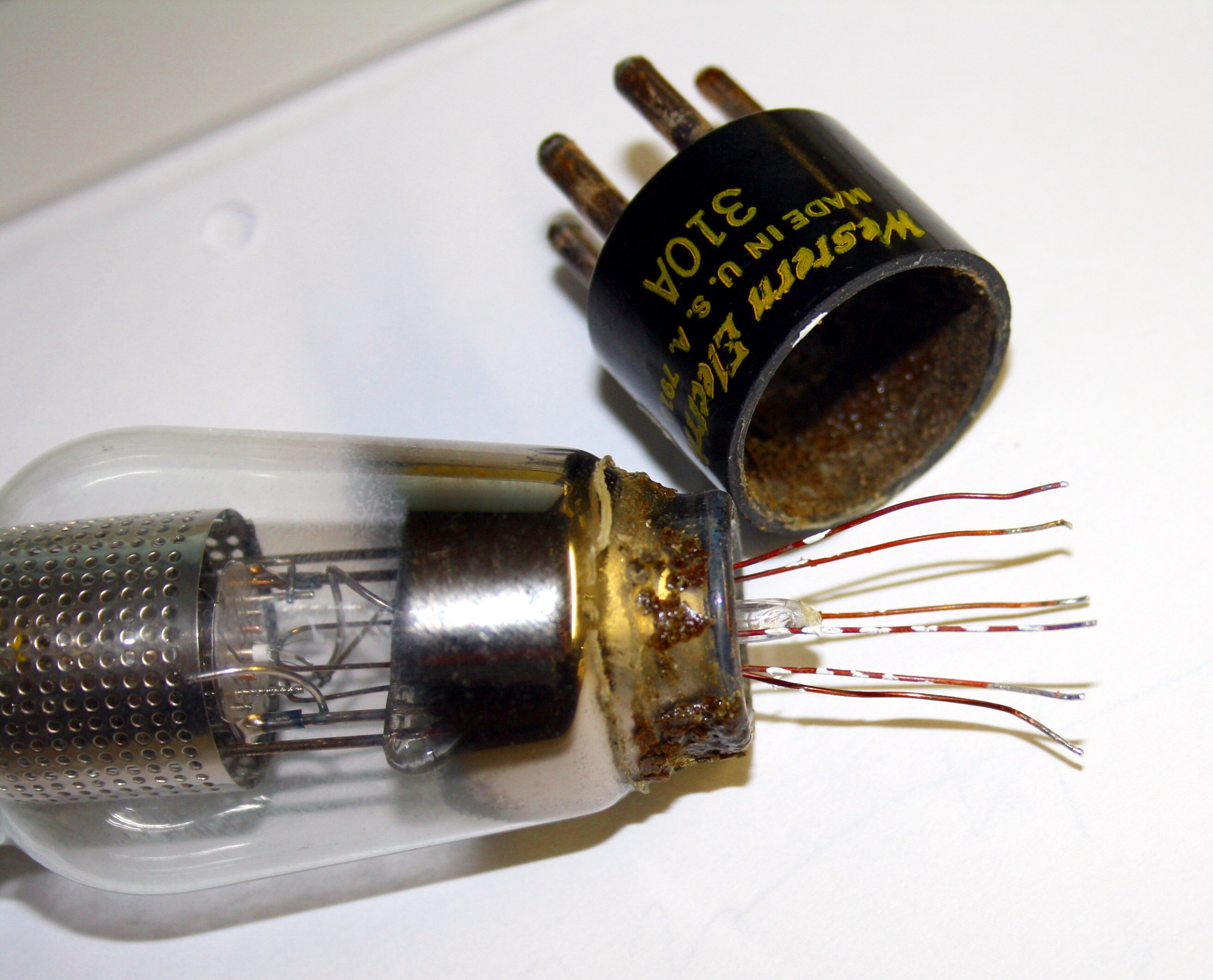 This is how the base came off the WE310. You can click the picture for a high resolution view. The markings on the copper wire are by myself, so I can put them back in the right way. Look how bend the tips are, from all of the wiggling. It was really lucky the glass pipe did not damage. A piece was already chipped off. (See the next picture)
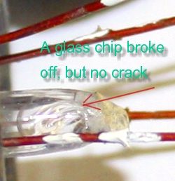 This a detail of the above picture, showing a glass chip has already come off the glass pipe, but it chipped off nicely without crack, so there is no damage.
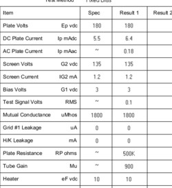 Test data of the tubes is magnificent. Really amazing and all perfect. This is the good part of those tubes. So WE quality after all. This data was made, after cleaning out all the old glue, and re-basing the tubes. Ok it costs the customer 100 Euro to do this for two tubes, but is was worth it for the customer, I think eventually the glass pipe would have broken if we didn't repair this.
The advantage of tubes having a grid cap, immediately gets visible during tube testing, because grid leakage current it absolutely zero. Whereas all tubes without a grid cap, we have always a few hundred nano amps. Note, grid current can be caused by gas (Very rare), or by grid emission (you need to heat up the tube very much=) or by plain leakage, over the mica, or the tube base from the inside. From my experience with tube testing, it is rarely gas, but rather all the other effects.
Grid current can be nicely calculated when you add a series resistance in the grid, and you measure Gm before you start. Any grid current will cause a voltage over that resistor, and this will change the grid voltage present on the tube base. That again will offset the plate current, and with the known transconductance you can calculate the change in grid voltage, which leads us to the grid current. So the tube is used to amplify it's won signal. So with WE310A, grid current was unmeasurable low. It was thanks to the grid cap, this tube did not have fart too much grid leakage. Even so the direction of the grid current tells you what it is, since grid emission is en electrical current coming out of the grid, whereas grid leakage makes current go inside at the grid.
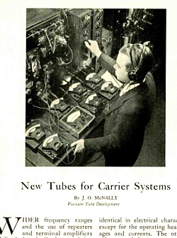 This nice 1937 Article about the 310A was send to me by Attila BALATON. - Thank you Atilla!