© COPYRIGHT NOTICE All Rights Reserved
Nixie bargraph Type INN9
(Last updated:
29-Mär-2012 15:16
)
This is a most amazing product! I have seen some Nixie bar graphs but they were very difficult to use, wit matrix configurations inside and too many connection wires. This bargraph here, has only two connections, it works like an ampere meter. Only difference is it has the offset voltage of the neon lamp of course. We well explain that later. Anyway, the illumination is so nice, much nicer than on this picture.
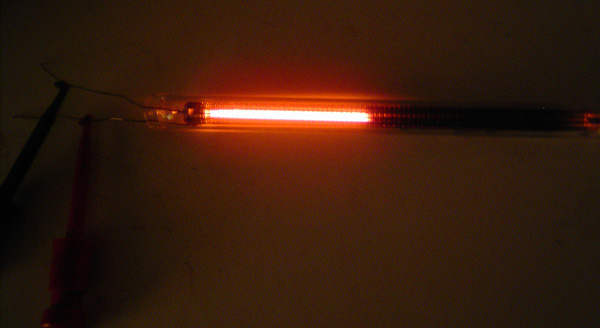
Night view
The way to operate this light bar is very simple. You need to connect a resistor in series, same as with a neon lamp. When you take a 10k series resistor, that gives a full scale at circa 220Volt DC, and a zero scale at 100Volt. All other voltages are shown nicely on an analog scale. So a good engineer can make a high voltage VU meter from this easily. If you take a simple and cheap high voltage transistor, and connect it like an emitter follower, you already have a VU meter, when you connect the transistor base to the output transformer primary winding and the collector to the power supply. It needs a few components more than just this, but not so many, and a circuit designer will understand the idea. You need to protect the transistor against negative base voltages. So making a tube VU meter is really a piece of cake. You can also use a small tube and connect it like a cathode follower, but for the beginning you should take a transistor, that's probably easier to start with.
Another VERY nice application is to monitor the mains voltage of your tube amplifier --- EXTREMELY precise. How is that done? You need only one resistor! You can take the DC High Voltage of the whole amplifier as a reference. (We call this voltage Vb) Suppose the mains goes up 5%, the DC High Voltage (Vb) goes up 5% too. So all you need to do is, put a resistor in series with the lightbar. (Connect the plus and minus correct!). Start with a value of 40k / 5Watt. This will give some reading. Then change the resistor until you found the right value that gives exactly half the scale when you connect it to the Vb. This value you need to find by experiment. Then you have a mark in the middle of the light bar. Any change of the AC voltage will also give a change of the light bar. You can increase the sensitivity by putting a power Zener Diode in Series. Like a 100V type, or put 2 or even three in series, depending on how high your Vb is. Like that the light bar will react more sensitive. When you have a known mains voltage, you can even calibrate the light bar.
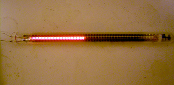
Daylight view
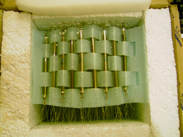
The holes you see in the screen are from the Anode. These are not lighting sections, the lightbar itself is analog. The holes are only to let the light through. II have absolutely no idea how they constructed this analog effect, but this part works great, and they are amazingly precise. These must have been incredible expensive, probably everything hand adjusted inside, and perhaps there is a resistor array inside. For the user that doesn't matter. All you see are two wires, and all you need to do is apply the right current to it!
Specifications measured by myself:
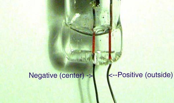
Positive connection: Wire on the outside of the glass. (Other wire is in the center)
Firing voltage 125V
Working voltage 100V
Current consumption at max scale10mA
Current consumption at Minimum scale 6mA
Light bar movement: 25mm per mA (one Inch per mA)
Length of light bar 9cm
Total Length including glass 13cm
Continues exceed of full scale: 30%.
Jac's formula to calculate Series resistor: Rs
Full scale voltage is called: Vfs
Rs = (Vfs / 0,012) - 8333
You can not get full scale below 150Volt. Any higher value is possible.
Originally packed... from 1970 or so.