About Amorphous Material, and core loss.
Transformers have four main kind of kind loss.
- Stray Loss, which is simply lost magnetism strayed into the air. This can be reduced by good geometry, and not under dimension everything.
- Copper loss. Thinner wire costs less, but has higher resistance.
- Capacitive loss, which results from capacitance between the windings mainly.
- Core loss, which by itself divides in Eddie Current loss, and hysteresis loss.
This article is about Core loss, but it doesn't pretend to be scientific, only explain what it is mainly about.
Eddie Current is a circular electrical current in the core itself, which is an energy loss, and it reduces the efficiency of the transformers.
What causes Eddie Current? It is a bit hard to understand when you hear it for the first time, but I will try with a pure text part. Just re read it a two or three times, and I expect it becomes clear then. We all know what a transformer is doing. The primary AC signal creates a magnetic field in the core, and this changing magnetic field will create the secondary electric signal. Very simplistic, this is how a transformer works. Suppose we use an iron secondary winding instead of copper, this would just as well be able to work, only of course at the much higher resistance of iron. Lets stop here. Suppose we want very much current to flow in this iron winding. How is that done? Well, we need to make the wire thicker, and the highest current would flow when we use only one very thick winding of iron, which fills the whole secondary package completely, and then short it. So it would be a circular piece of metal, looking like a big ring. If we use a rectangular cross sectioned wire, it would look like a piece of a pipe. That piece would get very hot if we mount that on a transformer instead of the secondary winding. Now lets look at the core itself! The inside half of the core carries half of the changing magnetic field, and it surrounded by.... the outside half of the iron! That outside half, will act as a shorted winding for the inside half. So to say like that the piece of pipe, in the previous example. And yes, that would give quite some electrical current, if the core would be made of a solid piece of iron.
This current is called the Eddie Current. In reality it does not flow at the outside of the core, in a single big loop. It flows everywhere, in very many small loops. Is this avoidable? Yes it is! Think again of this shorted winding. If we cut it open, no voltage can flow, even if the winding was there. So in that circular direction we have the lamination of the core, and in the other axis (90° on that) there is no lamination. This allows to propagate the magnetic field from the primary to the secondary, but there are no closed loops for the Eddie Current. The finer the lamination, the better the effect will be.
What causes hysteresis loss? This something totally different. We all know, a piece of iron can be permanently magnetized with a strong field (H). It is not much that remains, but it is there. This however cost a tiny bit of energy to get that magnetism (B) inside. This energy it cost us, can be seen from the following. Suppose we attach a strong magnet to a piece of iron. When the magnet is removed, the iron remains magnetized. Not very much, but it is, and it has cost us a tiny fraction of energy to magnetize it. (This energy was taken from the difference in force, once moving towards, and once moving away, and force was not identical because when going towards the iron was non magnetic, but when moving away, it was)
A more scientific approach for this, is given by the BH curve, which letters refer to to the relation of B and H. This is the relation between the external field (H) applied, and actual magnetization (B) inside the metal, resulting from this. A better word for B is magnetic flux. As you can understand, this depends on the material. Some will magnetize, like iron, or nickel, and some will not respond at all, like copper or tin. If the material responds, it can not do so without limits. At some moment, most of us have put some electric windings around an iron nail, and we found that gives a magnet, responding to the current. However, this magnet had some limits, a saturation effect, and at some point, it's magnet force would not increase, even if the current was doubled or tripled. This saturation effect, you can see from the BH Curve.

However, when the current was stopped, some small magnetism remained. This is the point P, where H is zero. This action cost a little bit of energy. So the electrical current was not only used to create heat, but some of if was used to make the iron magnetic. Can we remove this magnetism? Sure we can. We just reverse the external field H, and we come at the point Q. Again, this has absorbed some energy. From here the whole process goes into the other direction, and with AC field it reverses all of the time. At each cycle this tiny fraction of energy, was changed into heat. So the core warms up from this.
The result is simply, the higher the frequency, the higher the loss will be. The loss for one cycle is represented by the surface of the BH curve, and total loss includes the frequency, and how large the changing flux (B) is. The closer we come to the saturation (dotted line of B) the more we get this loss effect. The loss can come close to 100% if we just try to make the field stronger as the core can handle.
Where does amorphous material enter the game?
Amorphous material looks and feels like metal, and is of course magnetic too. Yet it is not a metal, but an alloy of metal and glass, and it fails several characteristic properties of metal, which are now replaced by those of glass. The most important reason why this is done, is the crystallization of metal, which is the key to making hardest steel, but it is only nasty when talking about magnetic properties.
Whereas metal always crystallizes after cooling down from melting, glass will not do so. Cold glass is a very thick fluid. The thickness is such, that we think we see no changes, but in very old church windows, it is found the bottom part is already thicker than the top part. That is because of gravity, and because it's a thick fluid. Main conclusion here: Glass will not crystallize when cooling down, but all metals do this below their melting temperature. Even so, the crystal structure is "alive". The metal builds new crystals over time, called recrystallization. Some metals do this more than others, and some alloys are very infamous for it. A very weird (an unknown cause) form of re crystal lis at ion is the building of tin whiskers ( See the article here on the right)
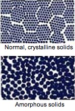
It is possible to melt metal and glass and mix this, approximately 1:1 When cooled down, the "alloy" will become what is called amorphous, translated as "shapeless". The refers to the microscopic picture. With metal, the crystals can be made visible, with photographic methods, and they form patterns. Fir this, think about the "sand" structure you may have seen when solder is cooling down, and you wait not long enough. These are the metal crystals. With glass + metal mixture, it becomes neither of the two. There are no crystals, but a much finer, structure of no particular shape. So the elementary magnets are smaller, and also the remanent magnetism is very very low. Meaning the "BH" curve is much nicer shaped, more ideal, but of course maximum saturation is lower, because half of it is glass.
Amorphous alloys ribbons are produced by rapid solidification of melted metals at very fast cooling rate. The makes the alloy solid before the atoms have a chance to crystallize. (WIth pure metal this will not work. You can influence the crystal shape by very fast cooling, like when hardening steel that way, but you cannot prevent crystallization). WIth Amorphous material, you can prevent crystallization, and create very beautiful BH curves that way. Whereas BH curves of pure metal are never as nice as amorphous. A wide variety of amorphous alloys is available to meet the wide range of needs of transformer designers
General properties of Amorphous Alloy Tape
- High permeability and low coercive force
- Low core loss and low exciting power
- Good temperature stability (working temperature -50°C ~ +130°C)
Typical applications of Iron Based Amorphous Alloy Tape
- Smooth current wave filters and PFC inductors
- Differential inductors in switch-model power supply
- Video and audio application
- Single phase and three phase transformer cores
- Power switch transformer cores
General properties of Amorphous Alloy Tape
- High permeability and low coercive force
- Low core loss and low exciting power
- Good temperature stability (working temperature -50°C ~ +130°C)
Typical applications of Iron Based Amorphous Alloy Tape
- Smooth current wave filters and PFC inductors
- Differential inductors in switch-model power supply
- Video and audio application.
- Single phase and three phase transformer cores
- Power switch transformer cores
Typical applications of Cobalt Based Amorphous Alloy Tape
- Magnetic amplifiers, noise suppressors, pulse transformer cores
- Differential inductors in switch-model power supply and common mode cores
- Transformer cores of high frequency power switch (30kHz~200kHz)
- Output filters and energy inductors
Disadvantages
- expensive
- very hard material
- gives sharp particles during production
Two Approaches to Amorphous cores
- The technical approach. For that you need to know and understand what the hysteresis of a transformer material is doing to the signal transfer. This is the higher permeability, lower coercive force, low core loss and low exciting power. Also the shape of the hysteresis curve is more linear, more square shaped. This gives a complex mix of new electrical parameters to amorphous cores, compared to normal steel cores.
- The listener's approach. Decide for yourself what sound you prefer. With today's modern core materials, amorphous cores are appreciated by "connaisseurs" of tube sound. Before that, there was already the use of this material for some high end moving coils transformers. Theoretically Amorphous material has a fraction higher distortion, but practically the sound is preferred by many.
Most comments are like this:
- more realistic sound picture
- more natural sound
- less listening to "the transformer"
Whatever approach may be right, for sure is, that despite the higher price, there is a fast, very fast growing interest in these products!