Problems with tubes and amplifiers
Contents
- Introduction.
- Consider all possible factors.
 Specific Amplifiers which need special attention (You are now here)
Amplifiers which need special attention
The following table, is about some personal experience, how to best deal with this model amplifier. We write it here, to make sure you use the products in the best possible way.
Air Tight ATM-1
Alan Eaton
BOTTLEHEAD PARAMOUNT
CARY Audio
Kondo Japan): Model KSL KEGON
Kondo (Japan): Model NERO
Manley 300B Preamplifier 'NEO-CLASSIC'
Mastersound 300B-SE
Mingda Meixing
Quad II 40
SUPRATECH
SUN Audio 300B Push Pull
SUN VALLEY SV-91B
SILBATONE Acoustics, KOREA
Tektron TK2A3-50M. Part 1.
Tektron TK2A3-50M. Part 2.
Tektron TK2A3-50M. Part 3.
VAC 30-30
VIVA Egoista 2A3
VTL 185
VTL. Model: ST 150
Welborne Apollo
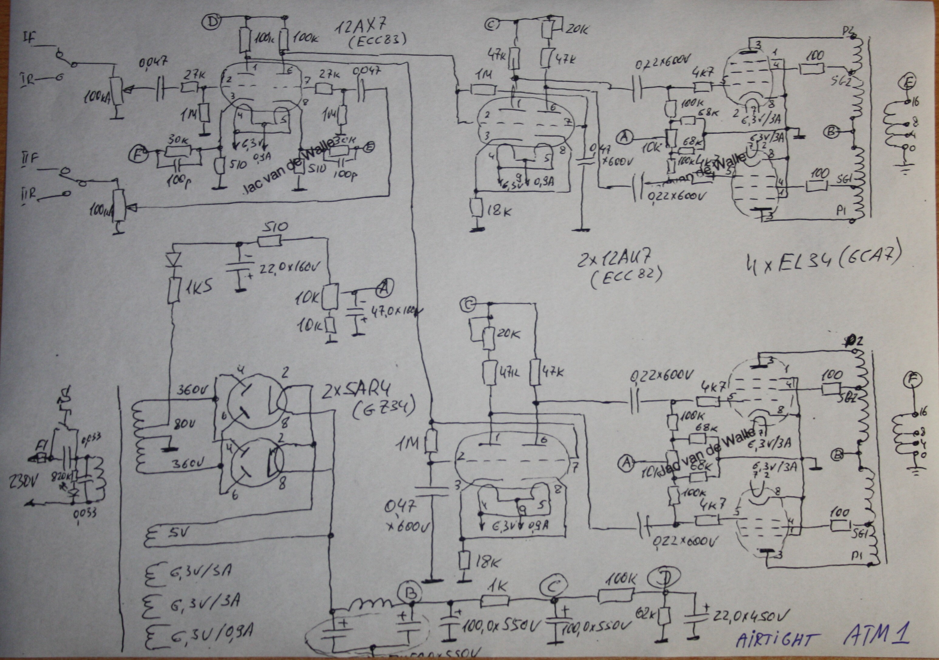
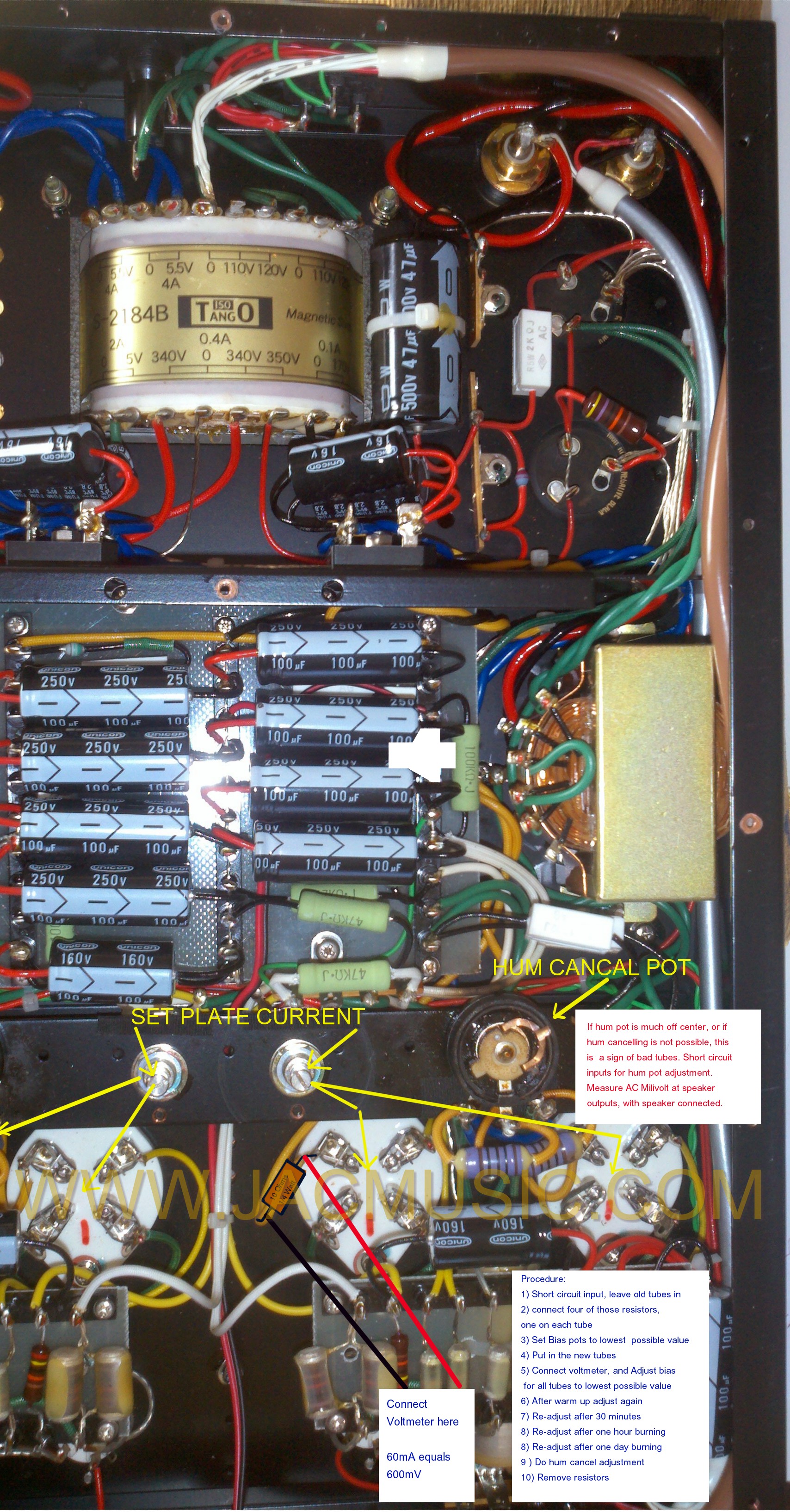
AIR TIGHT ATM-1The schematics were not available.
It should be well known, but I just mention it here anyway, you can not connect 220V amplifiers to 230V or even 240V without a mains adapting transformer, unless the amplifier is specified to do so. So basically all vintage products. Heater voltage tolerance of tubes is maximum 5%, but taking 5% as a default is a very bad idea also. Plug a 220V amplifier in 240V, means 10%. This will definitely damage the tube heaters, but also DC voltages and currents inside become wrong, and the mains transformer may produce mechanical hum. From this schematic it gets clearer what you need to look at. There is a phase reversal stage in here, with two ECC82, and it has an adjustment potentiometer. Adjusting this stage is 'overall' so it also affects the EL34 stage, which is drives. I would say, the best way is adjust this with an oscilloscope, so the El34 output stage is driven nicely symmetrical at full power. You need to do so, after bias adjustment. Now comes, what I think is important to know. These ECC82 tubes are Electro Harmonics tubes with the Air Tight logo stamped on it as well. Generally speaking, Electro Harmonics I have found to have a much larger parameter variation than NOS tubes, and the EHX ECC82 seems to draw less current than an average ECC82. So I would say, EHX is not an ideal tube for this, but it can be used. However, it was chosen, and since the amplifier is adjustable it doesn't matter anymore. Since the adjustment of the amplifier is an adjustment for the individual set of tubes, the best way is to have the amplifier re-adjusted by a real specialist after a tube change. Furthermore, since two random ECC82 can be quite different, you should never exchange those amongst each other by mistake. Needless to say, this can happen quickly! So the recommendation is, when you have those ECC82 replaced, you should always take what is called a balanced, matched pair. Something similar applies for the EL34. Each channel (Left and Right) has it's own balancing potentiometer, so in the end you'll end up with different settings for those two potentiometers. Once that is the case, you cannot exchange the EL34 amongst each other. So the moment you pull them all out, you should mark them carefully 1....4. This said, it is obvious, you cannot just replace the ECC82 and EL34 by 'some' tubes. The EL34 (Left and Right Channel, are controlled by the SAME bias voltage, so for that reason you can only put a matched QUAD in this amplifiers, and not two pairs. Overall this is a really very good schematic, and once adjusted correctly, the EL34 stages should work very good. Apart from what others say or do, my opinion is, best results will only come from a proper adjustment by using an oscilloscope. Disclaimer: This schematic was hand drawn from an ATM-1 and it may have mistakes in it. |
||||||||||||||||||||||
Alan Eaton AmplifiersSome others have discovered this glorious idea as well, I was told. We had an issue with EML Tubes, in an amplifier of which no schematic was handed out by Alan Eaton. So I had to create the schematics from looking at pictures, one of his customers send us. When I had the output stage on paper, I almost fell of my chair. Both 45 tubes are on ONE Cathode bias resistor. Sorry, but this is so dead wrong. This works only, if both tubes bias completely identical. Which is never the case. Moreover, when tubes age, their bias points changes as well. This is normal, and no reason to replace them. Either auto bias will correct this, or your hand-done bias is going to correct this. But with the Alan Eaton, neither of these... CONTINUE READING HERE. |
||||||||||||||||||||||
BOTTLEHEAD PARAMOUNTfirst, let me say here, this problem was solved by Bottlehead company in a very professional way. Sometimes a tube can violently spark inside the bulb.This amplifier is DC coupled. With such concepts, you always need to realize which tubes warms up first, and what this does to the bias of the next tube. What happens at warm up: The 12AT7 tube heats up slower than the 2A3. The result is, the grid voltage of the 2A3 for a few seconds is a lot higher than intended, in fact undefined, and probably POSITIVE. So you are only lucky if your 2A3 is not working yet at that moment. Most of the time though, the 2A3 will already be able to pull current. The better quality and the newer the tube is, the more current. Some tubes will draw so excessively much current at POSITIVE grid voltage, you blow off a tiny little chip from the filament coating, due to local overheating. What happens next, this loose piece becomes charged by free electrons, and once charged, the piece moves towards the anode. On it's way it gets hit by the electrons which are on the way to the anode too, but travel much faster. This is due to the fact that electrons have a high charge, and almost no mass. But they are incredible many. So the chip gets heated, and evaporates. The cloud of molecules get hit as well, and these get ionized, and the tube 'fires' with a spark. Like any gas filled tube, at that short moment, it has a very low forward voltage, and that blows the fuse. After that, the ions recombine with electrons, and the show is over, the tube works normal as before, but lost a tiny piece of the cathode. The remains of that is the white powder you sometimes find in much used radio tubes. They're proof of bad circuit design. 1) Amplifier Version with without the soft start.
2) Version with soft start option.This basically solves the spark issue with this amplifier, and this is a good, and mature product. However, if you want to switch the amplifier off an on again, you need to wait 20 minutes in between (or DAMAGE will occur). Don't forget this! Actually this is normal with many products. The only thing is, here you need to wait 20 minutes which is a long time, when you are waiting. 3) Heater voltage of 2A3 tubes.It seems the heater voltage of the paramount is too low. 2A3 must run on 2.5 V heater, tolerance on that is 5% for all brands 2A3. The heater voltage was reported 2.32V on the chassis inside, by one of our customers. This is by itself almost 8% off, and already below minimum. Moreover, because of 50mV voltage drop over each heater pin contact, there is another 0.1V drop. So with 2.32V at the socket solder connections, there is only 2.22V on the tube pins itself. It is recommended to have 2.6 Volts at the tube socket solder connections. To correct this, you can add an electrolytic capacitor, directly on the tube socket heater pins. Here is the text from Bottlehead company: 'This capacitor should be rated at 6.3V or more, and sized around 4,700uF to 10,000uF'. We recommend 10.000 uF. Conclusion
Note from EML: We recommend to retrofit all paramount with the Soft start kit, and also adjust the heater voltage of the 2A3 such that you have 2.6V DC on the solder connections of the tube socket, for the tube filament. General link to EML factory page about what causes a white spark: Read more here and here |
||||||||||||||||||||||
CARY AUDIOVery good and much recommended amplifiers. Of used as output tubes, they push the 300B or 2A3 tubes close to the limits, which is of course possible, but you need to be aware of what it does to the tubes, and lifetime in general. We recommend following:
|
||||||||||||||||||||||
Kondo (Japan): Model KSL KEGONThe issue is, the Parallel Single Ended output Tubes are hard wired in parallel, without a way to check and adjust the bias for each tube individually. This is very unwise to do, it assumes things about tubes which are not realistic. This amplifier hard-wires two 300B tubes in parallel. (see schematic) So, without any precautions whatsoever, the terminals of the 300B tubes are connected in parallel, and that's it. This is dangerous with random tubes. Since this method was used here, we need to see how we deal with this. It means, this amplifier will only work safe on a pair 300B tubes with special selection methods, and definitely cannot work on unselected 300B tubes, and also not on just any matched pair. What you need here is EML 300B tubes with factory tested grid voltage from -56V.... -60V, by the Emission Labs test method.
We give only guarantee when you use EML tubes like this. Another method, or another brand, it means guarantee will void. So please take care of the above, and you will love the results and the wonderful sound of this amplifier! A SERIOUS WARNING I have seen an 1991 circuit diagram without bleeder resistors on the High Voltage Caps. (!!!!!). This is extremely dangerous when you open the amp, even when 'off' the power supply caps can be charged still for hours or days. This is unlawful in all countries. All together this amplifier is regarded a potential problem maker. It should be serviced only by experienced people, and it needs special help tools to check the bias of each tube INDIVIDUALLY. We talk here about the JAPANESE KONDO, older version. |
||||||||||||||||||||||
Kondo (Japan): Model NEROThis amplifier hard-wires two tubes in parallel. It is generally the wrong to do this. We need to deal with some difficulties. It means, this amplifier will only work safe on a pair 2A3 tubes with special selection methods, and definitely cannot work on unselected 2A3 tubes, and also not on just any selected quad, of which the seller says they are matched very tight, but in reality he did not measure grid voltage at the NERO settings. So ask him for these values of the table below here, and if he cannot give you this, these tubes are not what you want. IN THE NERO, you need a quad of matched EML 2A3 tubes with specially tested grid voltage. First, you need to measure the grid voltage of the tubes, with a voltmeter. Voltage is measured against ground. This is in the working amplifier, with the old tubes inserted, presuming they still work. If so, do the measurement and let us know. For legal reasons we must say: Do such a measurement only when you are sure you are qualified for it. If not, let a good technician do this for you. We use the following table:
There are a few strategies to replace your tubes:
We give only guarantee when you use tubes under the above conditions. Otherwise, guarantee will void. So please take care of the above, and you will love the results and the wonderful sound of this amplifier! |
||||||||||||||||||||||
Manley 300B Preamplifier 'NEO-CLASSIC'this is not a complaint or a problem about this very nice pre amplifier. It is just we want to point out here, you cannot operate this amplifier with EML 300B-Mesh tubes. The mesh tubes are recommended to bias at Maximum 28 Watt, and it seems this amplifier runs the tubes above. It is a bit high for a pre-amp, but fair enough this is Manley's choice. So we recommend normal EML 300B, and since this seems an pre amplifier on 'steroids' also the 300B-XLS is a good candidate. |
||||||||||||||||||||||
Mastersound 300B-SEthis is one of the best 300B amplifiers I know. They are build around a decades old, very mature schematic, and the output transformers are great quality. The later types have electronic regulation for the heater voltage, making this amplifier very universal. This deals better with mains voltage variation, and allows other tubes than classical 300B only. However, they do need tube adjustment when you replace tubes. Failing to do the adjustment, may cause problems. You can check here, for some more information, about tube exchange. |
||||||||||||||||||||||
Mingda Meixingthis amplifier loads the 274B tube with an insane value of 100uF capacitor. This is absolutely not allowed by any tube datasheet. The 274B datasheet says maximum 4uF. Then, after the choke comes ANOTHER 470uf, and after this via a 2k resistor ANOTHER 470uF. This schematic was not made by using the tube datasheet. Meaning it was made by trying it out. At any problems, the designers will repeat as always '...how come we never had a problem with it...' This can cause the tube to spark, and sparking or not sparking, this may cause tube defects or later. You can check the amplifier's schematic at www.4tubes.com, this is an external link. |
||||||||||||||||||||||
Quad II 40 mono blocksFeb. 2026. The classic error. Rectifier capacitors exceed data sheet specifications. This seems to work in many cases, but unfortunately not always. So at a tube change, problems may occur for the first time. But even without visible problems, this will wear outf the tubes faster. A visible problems can be seen as a tiny spark in the rectifier during start up. This spark however, may also ignite the tube. If that happens, at the whole tube shorts. This gives a small flash, which blows the amplifier fuse. The 5U4G rectifier data sheet allows maximum 33uF. Which value is the sum of both the first and second capacitor, if the second capacitor is considerably larger as 33uF. At start up, the second capacitor is empty, and will saturate the choke for a short moment, if it is very large value. The choke at that short moment becomes only a copper wire. Causing both capacitors to be in parallel. Here with this amplifier, the first capacitor is already 82uF and the second capacitor is even 150uF, giving a total value of 232uF. Here is a cut out of the schematic. The question is always, what to do about this. The answer is: read the 5U4G data sheet of RCA, it explains how to use this rectifier. |
||||||||||||||||||||||
SUPRATECH Grange DHT LinestageOct 2022. The heater voltage of 300B in this amplifier is chosen 4.9V instead of 5V, by the designer. According to Mike from Supratech we are no tube specialists at all, and 4.9V is no problem. Well I said, it is as follows: If you exceed a critical parameter, guarantee voids. Everybody knows that. But in the same way, if you choose maximum deviation of a life time determining parameter, we still guarantee the minimum lifetime of the tube. That is just basics. With that particular amplifier, if you go 'somewhere below' normal heater voltage, but within specifications, you get 'somewhat' less lifetime, within specifications. |
||||||||||||||||||||||
SUN AUDIO 300B Mk2July 2022. This is a Push Pull amplifier, with too much start up current. 5U4G at 330Volt DC output, may only supply 120mA, with a capacitor of 40uF. What Sun Audio is doing, exceeds design limits of RCA 5U4G, which results in early tube wear out, or sometimes crack sounds during switch on. |
||||||||||||||||||||||
SUN VALLEY SV-91BNov. 2025. This is a good amplifier, but use it with 5U4G. This amplifier seems inspired on the Western Electric 91B. I was send this schematic, with the question if 300B-Mesh is used in this amplifier, what needs to be done. The tube dissipation needs to be reduced to a lower level, as needed by 300B-Mesh. Before going into how that is done, here are a few things which catched my attention.
How to use the 300B-Mesh tubeThe 300B mesh as we make them today (in 2025) are specified at maximum 28 Watt for maximum power, and 22 Watt dissipation for maximum life time. So you position yourself somewhere in between. Depending on what you find more important. With standard 300B that is not any different. It is used between 28Watt and 38Watt. Using the 300B-Mesh at a safe 24 Watt, would require to increase the bias resistor of 1k / 20Watt to a higher value. What value exactly, I can not say, but it will be in the range of 1500 Ohms. You could also do that with a switch, same was as TRAFOMATIC is doing with their Rhapsody, and switch between 300B-Mesh and 300B standard. Assuming the required value for 300B-Mesh is 1500 ohms, all you need is a 500 Ohms resistor in series with the existing 1000 Ohms. To switch the bias resistors between two values, this resistor of 500 Ohms is then shorted with a switch. |
||||||||||||||||||||||
SILBATONE Acoustics, KOREAIssue: Some of their amplifiers use these metal rings which are positioned too high. We have seen socket contact problems result from this, as tubes do not go inside as deep as they they should.
Also the glass contact to the chassis is a potential problem. The customer who owns this amplifier contacted the manufacturer, and the reply was, there is no support. Reason is, as they say, there is only one reference tube, and that is Western Electric. This answer was typical, and can not be accepted, because Western Electric never defined the diameter of the glass, at the point where it comes out of the tube base. When you let the glass disappear into the amplifier chassis, we say this is wrong to do, for power tubes. Even when they fit in, this can also cause failures with Western Electric tube. It heats up the socket from the inside, and it can cause problems. So Silbatone offered no solution. On my advise, the customer solved it himself in less than five minutes. For this he simply removed the 5mm distance holder, that you will find at the inside of the amplifier. This will bring up the whole tube socket 5mm higher. The ring can stay, and the problem was gone. That solved the whole problem afterwards. Why do amplifier manufacturers react so arrogant for no reason, that we have to write it here? We say here, real GLASS CONTACT or almost GLASS CONTACT to the chassis is definitely a problem. This amplifier builder may seem no problem initially, but if there is mechanical stress on glass, it can crack spontaneously after years. And yes, also with Western Electric, because their glass is also made of glass. |
||||||||||||||||||||||
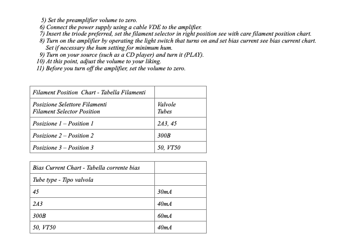
Tektron TK2A3-50M. Part 1.July 2020. This amplifier is not my favorite. At tube rolling it will not store the bias setting for the different tubes, which becomes a source of operating mistakes. Though this could easily have been done in hardware as well. The grid resistor is 100k, which is too much for most tubes. Ignoring this may lead to a total tube failure at random moments, after the tubes begin to see some use. The dangerous part of this is, you can not foresee this moment, and the tubes work completely normal until it happens. I had a case of selling two mint condition NOS 2A3 by RCA, which tubes both failed after 3 months of occasional use. Before sending, all data was 100%, and it was a perfectly matched pair as well. I tested them myself, and they were RCA NOS, top class. The failure mode in the Tektron was a bright red glowing anode, and and the amplifier stopped working. So the angry buyer send me back those 'Faulty tubes', and a spicy email with it, for me to digest. However I found damaged grids with both tubes. Some amplifier owners will not even know what a grid is, or what a grid resistor is, and how and why this can kill a good tube. Same with this buyer, he was over asked with the issue. He contacted Tektron, and they had a simple logic: Since the amplifier is good, logically the tubes were bad. After replacing them, the amplifier worked again. So that proved it was a tube problem. But was it really....? Here is the background of this amplifier. The tubes are used here with adjustable bias, not AutoBias. In most data sheets referred to as 'fixed' bias, but this means the same. The wording means you can "fix" the bias at an adjustable point. Not so with auto bias. The user can't change anything to auto bias. . When looking on the RCA data sheets from the 1930's they indicate greater care is needed with adjustable bias than with auto bias. That is normal. However, a very important thing RCA writes here, and that is not exceed the grid resistor value of 10k or 50k (depending on the build year of the tubes). So any lower value is possible, but not a higher value. I agree 10k is a low value, and nasty for design purposes. Designers always try to maximize the grid resistor, because that makes everything easier. For good reason, RCA managed to increase that value from 10k to 50k with a tube re design. Problem with that is, all tubes are all called "2A3". So be on the safe side, you should take 10k. So what happens if you take a higher value? I can tell you: Initially nothing. It seems to works just normal, and even for a such a long time, they get the wrong idea this will work for ever. However over time, sometimes the tube grid begins to develop some small amount of grid current. A little bit which doesn't bother much, but it gets more and more. This has to do with the tube getting older. Some tubes develop more than others. It's bit of a random effect, it is normal for most tubes, as long as it is within certain limits. If the grid current becomes too much, the tube will suddenly glow red or orange, and it's damaged. This sudden effect of the grid current, you can reduce it by making the grid resistor smaller. The tube manufacturer knows what is a safe maximum value. This is why a value of 10k or 50k is indicated in the RCA data sheet as an absolute maximum, and you should not regard it as safe design limit. Better is to keep a safe distance. Very bad is, to ignore this, and do what you want yourself. I asked Tektron, and they confirmed they used 47k. Which is pretty close to 50k. According to a July 2020 email I have from Tektron, such problems occurred before, with NOS 2A3 and NOS 50 tubes, but it is a tube problem, they say. So, a tube problem? No, I see it not like that, because you can not say if the owner is using NOS tubes which tolerate only 10k. Also I received pictures from the inside of this amplifier, and what do I see? A 100k bias resistor, not 50k as Tektron told me. You can put NOS 2A3 in there, but it depends if you have tubes of maximum 10k, or maximum 50k. I think the 10k types will not last very long. The 50k types probably work a long time on 100k, or even for ever. But the 50k is not without reason. You should not bet against RCA engineers. Otherwise it may go wrong at a later moment, random and unexpected. And no, this is not a tube problem, it's an amplifier design problem.
Quoted text from 1933 article. 'With fixed bias, this resistance should not be more than 10,000 ohms. Higher grid resistors may cause the grid to lose bias due to grid- current and the plate current will then rise so high as to damage the tube' Please note, this is just a text from an author in this (leading) magazine. (Also note, historically the word 'fixed bias' was used for what we call 'adjustable' bias today and it means the same. It means just the opposite of auto bias). Anyway, for RCA tubes, in the end what counts is only the RCA documentation, and this is here: 2A3 datasheet with maximum 10k (Until Manual 12) So this point needs A LOT OF ATTENTION . You can not blame the NOS tubes for this. This is a plain question of the amplifier itself. So my recommendation for NOS is MAXIMUM 10k. About the use of EML tubes with 50k grid resistor: These are an exception. Unlike with NOS tubes, with EML, 50k is no safety risk. EML grids are physically much larger and do not get very warm anyway. Unlike the RCA grid which is known to be fragile, and can suffer a thermal overload quickly, as we have learned with this amplifier. Tektron TK2A3-50M. Part 2.October 2020. Now it gets interesting! Another customer with a Tektron has damaged tubes. This user bought new 45-Mesh tubes from Emissionlabs. We build those ourself, so I know what is inside. They can not have grid emission, because they're made such that this can not happen. But AGAIN a customer who reports red-glowing anodes. So it was immediately clear we have a bias problem here, but what what problem can that be....? The buyer already contacted two dealers, and myself also. Then he send me pictures of the problem. And that explained it. Tektron has a manual saying you need to set the 45 tube to 30mA. Which is correct, and that is exactly what the customer did. Below is the picture he send me. But hold on.... Did he really set it at 30mA? Also look at the '5' below on those knobs What is it for? They are set at '530'. But it's worse than that.....
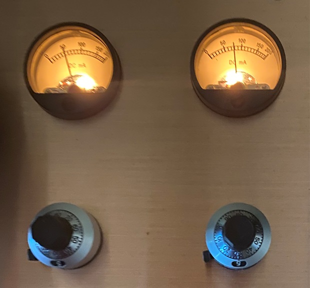
I did not question the setting, because I know the Tektron has meters. But stop..... how can the anodes glow red at 30mA? For RCA tubes that needs 150%, but EML need over 200% for that. Just look at the next picture, and it becomes clear what happened. I spoke with this customer via Face time. He understood the manual in such a way that the setting had to be done with those knobs. Because actually, that is what is written there. I asked him what to his opinion the meters were for. He said: I don't know. They are just to see if the tubes are working, because then the needle moves.
You can see the right EML45 running here at 75mA instead of 30mA. Well the good part is, the EML tubes survived the attack. Tektron TK2A3-50M. Part 3.December 2025. We had a pair of 300B tubes, of which one refuses to bias well after being stored. Same situation as always, the owner already knows it is a tube defect. He did not take my offer to send in the tubes for professional testing. I have the equipment here, to find out if this is a tube error, or tube abuse, or just exceeding the use hours. So this case is open, until the owner perhaps changes his mind. What I do know: Another Tektron involved. |
||||||||||||||||||||||
VAC 30-30Good amplifier, but it does put quite some stress on the 300B tubes. Which is just within data sheet limits, so yes it is possible. But we all know, that this is not the key to long life time. We were in contact with the manufacturer to see if the 1.5 Ampere 300B-XLS tubes can be used here. They said, they will check it, and the answer is probably yes. There was never any answer, so please ask them yourself if you need to know. |
||||||||||||||||||||||
Viva Egoistic 2A3
We do not sell 845 tubes, because these are too problematic for tube dealers, but the VIVA EGOISTA 845 'shoots the bird' as we say it in German. If this causes a glass breakage, the tube anode of the 845 is right out in the open, with lethal voltages on it. Most 845 circuits work on 850 Volts or more. Just imagine, you break the glass with the cable of your head phone. I would not want to wear this head phone on my head if that happens. |
||||||||||||||||||||||
VTL 185Adjustment range is not very high, and (good) new KT88 tubes may draw not enough current. When replacing with Svetlana S-logo, Sovtek or EHX, it is recommended to use KT88 that show test values much above 60mA, by the factory test method. For other brand tubes we don't know the limits, but you need the higher current ones here as well. |
||||||||||||||||||||||
VTL. Model: ST 150Adjustment range is not very high, and (good) new 6550 tubes may draw not enough current. When ordering Tung-Sol 6550, it appears you need tubes that are tested above 60mA, by the factory methods. The same values apply for EHX 6550. |
||||||||||||||||||||||
Welborne ApolloThis is a very nice amplifier, much recommended products! However the company has recently disappeared into a black hole, and there is no support now. We see often, users want to replace the KR842 tube if used in there, by original 520B. Please take good care when doing so, because different tube numbers always indicate the tubes are indeed different. So by ignoring this you can have problems with the tubes or the amplifier. Running EML520B-V3 in the Appollo.You have to be careful with tube replacement, if you just replace the tube you find in the amplifier by the same type. Sometimes, mistakenly a wrong tube was in there. So that's why it damaged, and by simply replacing it, you will only repeat the problem. Sometimes the amplifier may have been modified to adapt for some other tube, and you would replace it perhaps by the original tube. Also a problem. Also there is bad and dangerous confusion with tube numbering of AVVT, VAIC, AND KR. For that reason we did not adapt this tube number system at EML. Though we build the same tubes, we gave them other numbers, so not to get involved in the confusion too. 25 years ago, this amplifier was made for the old VAIC VALVE 52B, but soon after it's introduction, the great Wizard Mr. Vaic was introducing variations in heater voltage and heater current. Yet one way or another, EML520B-V3 can be used, if the HEATER VOLTAGE IS CHECKED AND ADAPTED. This is regardless of what the previous owners have put in. We recommend replacement by the EML520B-V3, but at replacement, two things have to be verified:
|
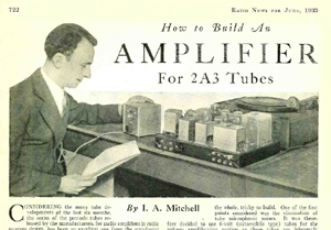 Here is a copy of a most excellent article
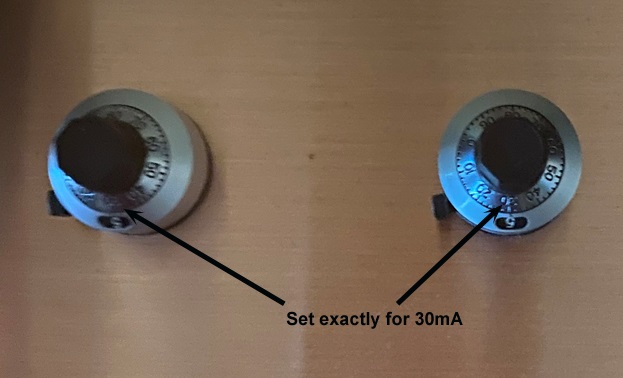
 This is the weirdest thing I saw since a long time. The tube glass touches the chassis. Our EML tubes do not even fit into the hole, but also other brand tubes which are smaller, have a high risk, the tube glass touches the chassis. This will give a high temperature gradient of the glass, and there is risk of glass breakage. Everybody can do his own crazy things, but this is beyond any acceptance level for me.