Electron Engine ™
Printed Circuit Boards by Emissionlabs
Preliminary page.
EE60. Universal Experimenter PCB. Version V2.
Board Order Number: 311-060-90
WE SUPPLY ONLY THE BARE PCB.Tube sockets can be ordered with it.
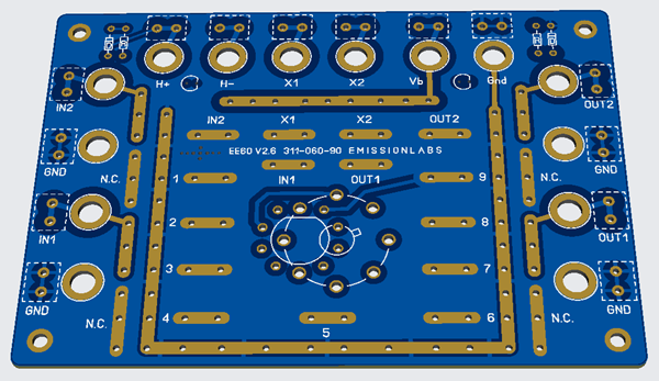
USER SIDE oF EE60-V2
At the USER SIDE, the electronic parts are mountded. If some parts are definitely used, and you want to keep the side simpler, these parts could be mounted at the solder side as well.
In the large holes, low cost 6mm screw, banana sockets can be mounted, screw terminals can be soldered in, or simply a wire can be soldered in as well.
 When using banana sockets, also "banana to BNC" adapters can be plugged in, the dfistance is excactly right for that.
For Plate Cap or Grid Cap tubes, connect the caps to "N.C." pads, at the user side. N.C. stands for "Not Connected",. These are blind solder pads only. Or, alternative, with some Octal tube data sheets, the plate cap is referred to as "9th Pin". In that case you can use Solder pad #9. because with Octal sockets, there is no conection to that pin anyway.
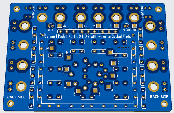
At the solder side, the heater connection of the tube is made, with wire pieces. Just connect the square H+ and H- Pads, to the square pads of the socket. Also, specific small parts which definitely will not change, might as well be mouned at the solder side.
Features:
- Multi Layer PCB with ground plane at each side. Size 14.5x 10cm.
- Can be used for pentodes or double triodes.
- Use a 9 Pin noval socket, or 8 Pin Octal or Loctal socket.
- CONNECT THE HEATER: At the back side are solder pads for this. Look at the picture below with the green wires. This is for 6SN7, it needs the heater at Pin 7+8. By this method, the top side of the PCB becomes tidy. With a pentode, most circuits connect G3 to the Cathode anway. All such permanent connections you could made at the back. So the user side stays easier to work on.
- X1 and X2 are universal connections with banana plugs. For instance, when you are interested in the bias voltage, connect X1 to the bias resistor, and with banana plugs, connect a voltmeter between X1 and ground.
- The High Voltage (Vb) has a blue warning LED.
- The heater voltage has an orange "ON" LED, which burns at AC, or DC. When heated DC it burns only when the heater voltage is connected the right way.
- FOR each amplifier stage, use it's own board. You will like this system! Amplifier boards are blue. The power supply board is red.
Connectors:
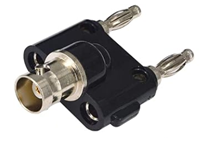
- Use connect low cost Chinese banana plugs for the board. You need the ones with a very short piece of 6mm thread at the back. So not the ones with a very long 4mm thread sticking out, because these are for instrument panels. Those 6mm are intended for PCB mounting. They are amazing low cost in quantities of 20pcs, directly from China. Here is a picture.
- Alternative, use PCB solder terminals. Or, just solder wires directly.
- The signal plugs (IN and OUT) have the right distance to connect a banana to BNC adapter to it. (See below. at the bottom right, is a red BNC cable connected)

Initial testing of a 6SN7 circuit, with EE60-V1 PCB.
- I always make a rough (messy...) test first, as shown here above, with old parts from the junk box. When that works, I re wire the board with final parts, and move wires and uninteresting parts to the back This circuit here, is a DC couples dual stage amplifier, to drive an 300B tube. Still refining the circuit, but the PCB is fine.

Connecting the heaters of a 6SN7 tube, with EE60-V1 PCB