Electron Engine ™
Printed Circuit Boards by Emissionlabs
Secondary Board for: LL1620, LL1623, LL1627, LL1679, LL9202, LL1663, LL1664, LL2765, LL2774.
2. ![]() Secondary Boards (You are already here)
Secondary Boards (You are already here)
We have copyright on this design.
This is a Lundahl Approved Product
![]()
'Hello Jac, It took some time but now I have deciphered your EE16 + EE17 boards. Very pretty! And yes, you can write that this board set is approved by me'.
Per Lundahl, by Email, Oct 7th, 2022
How these PCBs are used.
First of all, there is no more need, to understand the difficult 'Alt' wiring of the larger transformers. Just look in the table below here, and you will find the transformer and the right EE-Board for the impedance of your choice.
The boards work on all Versions, SE, PP, UL, CFB, PPZ.
| SE | Single Ended |
| PP | Push-Pull |
| UL | Ultra Linear for LL1663 and LL1664 |
| CFB | cathode feedback for PP amplifiers |
| PPZ | Parafeed. Combines the best of SE with PP |
Part #1. SINGLE Impedance, for the small transformers LL1663 and LL1664.
Line |
Trans-former |
Input Impedance |
Output Impedance |
Board used |
Remark |
1 |
5k |
8Ohms |
EE63 |
UL Tap at 50% (*) |
|
2 |
3k |
8Ohms |
EE63 |
UL Tap at 50% (*) |

- By connecting the tube anode(s) and V+ to the left side, or right side, the choice between SE or PP is made.
- EE63 board can be used for Push Pull , Single Ended, or Parafeed (PPZ). If used PP, Ultra Linear Taps can be connected.
Part #2. MULTI Impedance for head phone transformers LL2765, LL2774

Part #3. MULTI Impedance for the large transformers, LL1620, LL1623, LL1627, LL1679, LL9202
EE16 and EE18 Output Boards
There are THREE ways to use these:
- Single impedance
- Dual impedance with on-Board switch
- Dual impedance with external switch board.
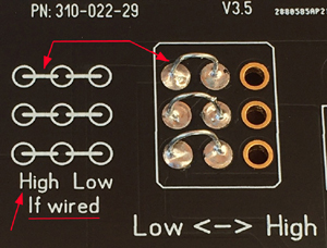
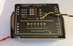 First way to use it: This can be done with wire pieces (on EE16 and EE18), or solder bridges with EE32. Like this, the impedance becomes fixed. On this picture, the board is wired for HIGH impedance. It is the same as what the switch is doing. (See next picture, below here).
Be careful with wire pieces. The 'Lowh<->High' text indicates to direction of the toggle switch. The wire pieces need to be mounted in reverse: Also look here.
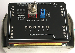 Second way to use it: With EE16 and EE18 it is possible to mount the switch directly on the PCB. In that case, impedance selection is not fixed, but it can only be done at the inside of the amplifier.
 Third way to use it: To EE16, EE18 and EE32, it is also possible to attach an external switch board. This allows to change the impedance at the outside of the amplifier. The switch type we supply, has silver contacts inside.
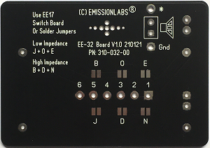
EE32 Output board
The special lay out of the LL1679 transformer required a dedicated board.
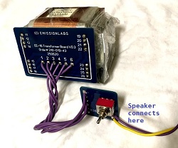
- This board can be used stand alone, or with the optional switch board EE17.
- If used with the switch board EE17, the speaker can be connected to the switch board, or to the EE32 board.
- On the EE32 Board the speaker can be soldered with wires, using the connections * and Gnd. Or, use a PCB Screw Terminal (not supplied with the board).
- This board is tin-plated.
- Low impedance: Solder Bridges O + E + J
- High Impedance: Solder Bridges B + D + N
- Use Switch Board EE17: All bridges open
EE17 and EE19, External Switch Boards
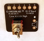 The loudspeaker can be connected directly to the transformer board, or to the external switch board. This is your own choice. Since the external switch board is probably going to be located near the loudspeaker terminals, the speaker can be connected to the switch board directly. This really makes the wiring short any easy. But there are also speaker connections on the transformer board. Just mount everything, as you like it most.
EE15 Primary Board
used for: LL1620, LL1627, LL1623, LL9202
Sorry, we have no primary board for LL1679.
For nicer wiring of the PRIMARY side, use EE15. As you see here in this picture, just solder it on the transformer, and you have two wires for the SE (or PPZ) connection. For wiring the same transformer Push Pull, just solder the wires in the box for 'PP'.
In addition, EE15 provides 50% Ultra Linear taps to all transformers, SE or PP.

 Example of use
LL1623-60mA with the '45' tube, Single Ended. Primary impedance 5k6, Speaker impedance 16Ohms.
Look at Line 13, in the table below here. You see there EE16-EE17, and 8 and 16 Ohms. Wire EE16 with three wire pieces for "High" which is here 16 Ohms, and solder the board on the transformer. Just as on the picture. - Finished!
Alternatively you can mount a switch on EE16. This will switch from 8 to 16 Ohms. Or, connect the external switch board EE17. This will also provide the speaker connections directly from EE17. Very convenient.
On the primary side, solder EE15 on the transformer - Finished!
Within just minutes you have it all working, and guaranteed to mistakes.
Possible Output impedancesSelect here first: Your primary impedance Then:
Two Output impedances of your choice.
|
|||||||||
Line |
Trans-former |
Input |
Output Power SE |
Output Power PP |
Set switch 'Low' |
Set switch 'High' |
Input Board |
Output Board |
Switch Board |
4 |
650Ω |
50W |
100W* |
4Ω |
8Ω |
EE15 |
EE18 |
EE19 |
|
5 |
1k2 |
25W |
100W* |
4Ω |
8Ω |
EE15 |
EE16 |
EE17 |
|
6 |
1k2 |
25W |
100W* |
8Ω |
16Ω |
EE15 |
EE18 |
EE19 |
|
7 |
1k6 |
50W |
100W* |
4Ω |
8Ω |
EE15 |
EE18 |
EE19 |
|
8 |
2k3 |
13W |
62W |
8Ω |
16Ω |
EE15 |
EE16 |
EE17 |
|
3k |
25W |
100W* |
4Ω |
8Ω |
EE15 |
EE16 |
EE17 |
||
10 |
3k |
25W |
100W* |
8Ω |
16Ω |
EE15 |
EE18 |
EE19 |
|
11 |
3k3 |
50W |
100W* |
4Ω |
8Ω |
EE15 |
EE18 |
EE19 |
|
12 |
4k5 |
20W |
100W* |
4Ω |
8Ω |
** |
EE32 |
EE17 |
|
13 |
5k6 |
13W |
62W |
8Ω |
16Ω |
EE15 |
EE16 |
EE17 |
|
14 |
6k |
25W |
100W* |
4Ω |
8Ω |
EE15 |
EE16 |
EE17 |
|
15 |
6k |
25W |
100W* |
8Ω |
16Ω |
EE15 |
EE18 |
EE19 |
|
16 |
6k5 |
50W |
100W* |
4Ω |
8Ω |
EE15 |
EE18 |
EE19 |
|
17 |
9k7 |
9W |
45W |
8Ω |
16Ω |
** |
EE32 |
EE17 |
|
18 |
11k |
25W |
100W* |
4Ω |
8Ω |
EE15 |
EE16 |
EE17 |
|
19 |
11k |
25W |
100W* |
8Ω |
16Ω |
EE15 |
EE18 |
EE19 |
|
20 |
11k5 |
13W |
62W |
8Ω |
16Ω |
EE15 |
EE16 |
EE17 |
|
21 |
23k |
13W |
62W |
8Ω |
16Ω |
EE15 |
EE16 |
EE17 |
|
| * Output power is limited at 100 Watt at 4Ω. Switch may only be used with the amplifier off.
** For LL1679 there is no input board. The input side has to be wired by hand. |
|||||||||
Part #3. Switching the INPUT Impedance. OPTIONAL use.
Though this is not the normal way to use it, we still encourage you to try it. You loose nothing, but you may achieve something interesting. Explained below here:
A difficult part of the amplifier design, is find the right primary impedance. So just assume, you will always use 8Ohms speaker, and the primary impedance is 3k3. So no need for switching? Well... think about this: The damping factor of the bass chassis, is roughly doubled when the primary of transformer is increased to 6k. You may like that sound a lot more, but you lose some volume. This means when you really need the maximum volume for hard rock, or fun, stay with 3k3. Generally, perhaps at moderate volume, you would get better sound using 6k. In addition, this makes you loose 3dB hum and noise. (Yes!). So you see, sometimes, the one is better, sometimes the other. Why not make it switchable? Look in the table below, and it is line 36, for this particular example, which requires board EE18, and switching board EE19 attached to it.
The intention of the table below, is that you don't need to calculate this, and don't need to understand the way of achieving this. Just use the right PCB and you are done. (If you insist on a the details, read the notes about it).
| Line | Trans-former |
Switch to 'Low' Position |
Switch to 'High' Position |
Board + Switch Combination |
Two Input Impedances with 4 Ohms speaker |
||||
22 |
650Ω |
325Ω |
EE18-EE19 |
|
23 |
1k2 |
650Ω |
EE16-EE17 |
|
24 |
1k6 |
800Ω |
EE18-EE19 |
|
25 |
3k |
1k6 |
EE16-EE17 |
|
26 |
3k3 |
1k6 |
EE18-EE19 |
|
27 |
6k |
3k3 |
EE16-EE17 |
|
28 |
4k5 |
2k6 |
EE32-EE17 |
|
29 |
6k5 |
3k3 |
EE18-EE19 |
|
30 |
11k |
5k5 |
EE16-EE17 |
|
| Line | Trans-former |
Switch to 'Low' Position |
Switch to 'High' Position |
Board + Switch Combination |
Two Input Impedances with 8 Ohms speaker |
||||
31 |
1k2 |
650Ω |
EE18-EE19 |
|
32 |
2k4 |
1k2 |
EE16-EE17 |
|
33 |
5k6 |
3k |
EE16-EE17 |
|
34 |
3k |
1k6 |
EE18-EE19 |
|
35 |
2k3 |
1k2 |
EE16-EE17 |
|
36 |
1k2 |
650Ω |
EE18-EE19 |
|
37 |
6k |
3k3 |
EE18-EE19 |
|
38 |
11k5 |
6k |
EE16-EE17 |
|
39 |
9k7 |
4k5 |
EE32-EE17 |
|
40 |
11k |
6k5 |
EE18-EE19 |
|
41 |
23k |
11k |
EE16-EE17 |
|
| Line | Trans-former |
Switch to 'Low' Position |
Switch to 'High' Position |
Board + Switch Combination |
Two Input Impedances with 16 Ohms speaker |
||||
42 |
2k3 |
1k2 |
EE18-EE19 |
|
43 |
4k6 |
2k3 |
EE16-EE17 |
|
44 |
11k5 |
6k |
EE18-EE19 |
|
45 |
23k |
11k |
EE16-EE17 |
|
46 |
5k6 |
3k |
EE18-EE19 |
|
47 |
11k2 |
5k6 |
EE16-EE17 |
|
48 |
19k |
9k7 |
EE32-EE17 |
|
49 |
23k |
11k |
EE18-EE19 |
|
DIMENSIONS:
- EE15, EE16, EE18: 92 x 66mm
- EE32: 97 x 69mm
- EE17, EE19: 40x 43mm
- EE63: 67 x 58mm
A very useful application is also when the speaker system is extremely high efficiency, like it can easily happen with the AVANTGARDE Systems, or similar horn drivers. Read also this article. The amplifier has in fact too much output power, and the remaining hum will become too loud. In that case, switching to the next lower OUTOUT impedance will reduce the hum by 50%. Just try it out, and you will see!
Mounting of the transformer board.
- Do NOT rotate the board, upside down by mistake. Though it seems to work, transformer windings become connected not ideal. This may give less good frequency range. So there is this white U-Shape marking on the board. When this is oriented the same as the transformer, the board is mounted correct.
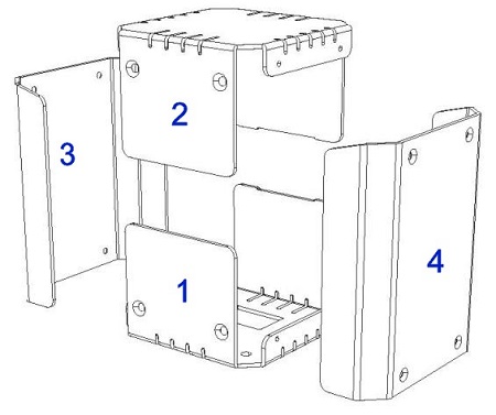
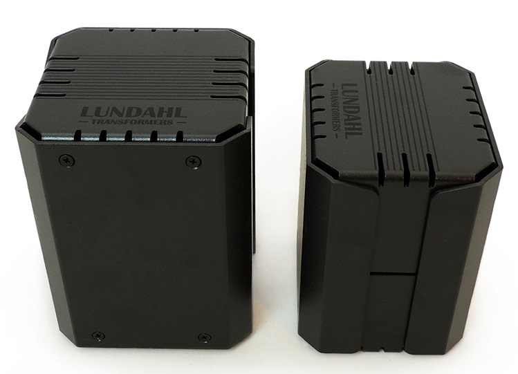
- The transformer board will fit nicely inside those LUNDAHL covers. Only the flip switch can not be mounted on EE16 or EE18 any more. So either the impedance has to be fixed, or use the external switch board,
Notes
It is not necessary to read all of this. But it does reflect a little bit the things I learned and found out while using those transformers. Perhaps you find some parts of this text useful.
Speaker Output transformers are always inter sectioned. So there is a primary layer, a secondary layer, a primary layer, etc. This will improve the high frequency performance. The disadvantage of this is, any isolation failure between primary and secondary, would lead to the DC high voltage on the output circuit. To prevent this, the 'cold' side of the speaker output (the 'Black' terminal) must always be connected to the chassis, and the chassis to safety ground. This is the connection NOT marked with a star (*) symbol. The 'hot' side is marked with a star (*) symbol, and is connected to the 'Red' speaker terminal. The switch should be grounded as well, so mounted at a metal part of the chassis.
For safety, the speaker connector (BLACK TERMINAL) must always be grounded to the chassis.
Tapped windings or not?
Tapped windings, are easier to use, we all know that. But for constructing a good transformer, that is not the best. Reason is simply, for most configurations, a part of the winding stays unused. This unused winding is in the way. It obstructs the magnetic path for the used windings, and it prevents good functioning of the 'layering'. So where is the unused winding, the layering can not do it's good work. Also this forces the remaining part of the winding to be made with thinner wire, because space inside the transformer is limited. Such transformers are simply not really the best, and you won't find them with Lundahl. We are aware DIY require such tapped transformers, but that is because the reasoning behind it, is not really known, or not understood at all. The result of a tapped transformer is ALWAYS, these work as specified if both primary and secondary are used at maximum impedance. But however, the further down you tap them, the more frequency roll off they will give, and the higher the power loss due to copper resistance and no good use of the magnetic path. Needless to say, this problem is carefully hidden in their data sheets, so we just talk about it here :) . If the problem is not hidden, they must give frequency roll off data, and power loss data, depending on the tap configuration. If that is missing, well this is why. For SE transformers, the loss of Inductance is considerable, simply because not all windings are used at a tap. This problem is hidden by specifying the transformers at 30Hz low frequency, and using 3dB for that. Meaning, you loose 50% of the signal at 30Hz. Judge for yourself if that is no problem, but please read data sheets carefully when it comes to roll off, and power loss. So transformer efficiency is something they should not 'forget' to mention. It is not fun to pay 1000's of Euro for a top class project, and then loose 10% of the output power in the transformer.
So by tapping, efficiency, inductance, and frequency roll off, it all suffers. This is why Lundahl company is not doing so. The lower impedance is created by putting the output winding layers in parallel, making copper resistance low, which is something needed, if working at 4 Ohms only. The same windings are put in series to get 16 Ohms. This will raise copper resistance, but at 16Ohms, that would give the same efficiency still. At 8 Ohms it is a combination of serial and parallel.
The above explains the advantage, and it is why specs of Lundahl transformers are better. The disadvantage is having to wire this by hand. First, you need to do this, and second you can make a mistake with it. The idea to make a switchable circuit for this, was actually mine, but I got stuck with the complexity. After bringing this up to Per Lundahl, he came up with a very clever circuit for this. It works with Jumpers, connected quite difficult. Yet by rearranging the schematic, I found a way to replace these jumpers by a 3-pole switch. Technically it works the same.
Moreover, but that is too difficult to explain in detail, tapping increases the susceptibility of the transformer to external magnetic fields, such as radiated by the mains transformer, and audible hum can be caused by this.
Output Impedance vs input Impedance - Notes for table #2.
Sometimes people think a transformer has a defined input impedance. This is not so! If you take a transformer, wipe off the product number and give it to an expert, he will not be able to tell you the input impedance. That is because input impedance depends on the load impedance you connect to the output. When you say, ok it is 8 Ohms. Then he can tell you. When you say it is 4 Ohms, he will give you a totally different number. On top of that, most speaker have not the impedance as written on it. If they write 8Ohms on it, it can be 8Ohms indeed, but it may as well be 6 or 12 Ohms. Frankly, it's a big mess. Even so, loudspeaker impedance is not constant over the frequency range, and varies wildly (upwards) in the low frequency range. Read more about it here....
Damping Factor. The next good thing, which happens, the amplifier has such a thing as damping factor with the bass loudspeaker, and this gets improved. The less it is damped, the louder the whole speaker will be, but the more muddy the bass sound will be also. This is always a compromise between what the amplifier can do, and what it should do. Damping factor is defined as REAL load (for instance 8 Ohms) divided by REAL output impedance (for instance 1,6Ohms, and then damping factor is 5. When connected the EE16 board with a 3k transformer to an 8 Ohms speaker, and then switch the board to 4 Ohms, this DOUBLES the damping factor. You can try it, and it will improve the bass quality (faster bass), and reduce the amplifier microphonics and hum. This will be on the cost of maximum volume, so if maximum volume is more than you need anyway, this may be a sound you even prefer.
The required output impedance
This should fit to your speakers. Just not always 8 Ohms speakers work best at an 8Ohms Output. Most of the time yes, but just not always. Frankly many speaker builders compromise on the output impedance, to be able to use the chassis they want, or put some chassis in series or parallel. There is really very much compromising done here. So an '8 Ohms' speaker is really only 8 Ohms in theory. Add to this the impedance in the low end is seldom as specified. A typical issue is also when the amplifier is too loud for the speakers. This will make hum and noise louder too, and you may not like that. In such a case, switching the output to 4 Ohms, will not compromise sound quality, but it will reduce noise by half. So I always recommend, to find out by your own hearing tests, what sounds best. And no, that is not always connecting the speaker to the specified output impedance. Here comes the point, with a hand-wired configurations. Suppose you have 16 Ohms speakers, and you wire the transformer for 16 Ohms, and it sounds good. What will you do? You will say you are finished. Nobody is motivated to take it apart, only to try another impedance, which is supposedly wrong anyway. This is however such a nice feature, to be able to try this out, and it would be a pity not to do so.
Transformer pin arrangement of these PCBs.
Sometimes, users want to verify if these PCBs have the same connections as the Lundahl data sheets write. A first test seems to confirm, we made PCB errors, and we are asked to comment on these findings. We build these PCBs since a few years now, and of there were errors, we would know it of course. The explanation is another. These transformers are symmetric constructed for a good part, and this allows us to inter change specific coils. We have been doing so to improve the PCB lay out. Meaning, resulting tracks are shorter, and the lay out becomes better quality. It is not possible to swap random coils, but as long as inter sectioning is kept intact, a swap is possible. Just as an example: for LL1620, 'Alt-D' you will see in the data sheet pin 11 and 12 are connected. This puts those two coils in series, and the resulting coil is found on pin 19 and 20. But you may as well connect 19 to 20, and then the resulting coil is found on 11 and 12, which gives exactly the same signal and same sectioning. If that resulting coil, for best PCB lay out, would be needed close to 11 and 12, then we swapped the coils, of course. This is why some of the connections are as in the data sheet, and some are not.