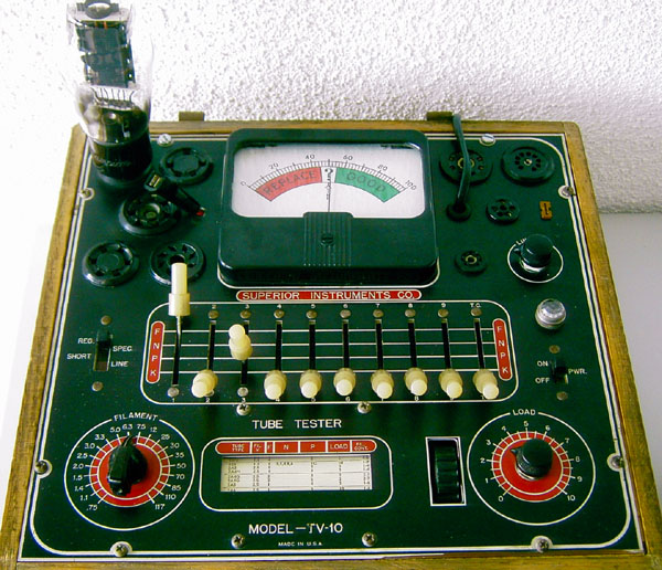
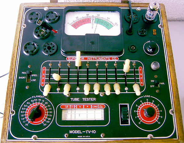
This piece of historical equipment is an oldie but a real goodie. It is surprisingly accurate, and identifies the bad tubes indeed. I have tried it, with several known to be good and / or bad tubes. It had a second transformer build in, the adapt it for 230 Volts, and it has a European mains connector. The electronics is all original, not changed or repaired, and no repair was due. It seems to be very little used, alls switches work smooth. The leakage test is very sensitive. All in all this tester is of very good quality. It can test any tube that it has the sockets for. If you want to test a later model tube, you can take the settings of a similar tube, with the same pin out. For instance the 300B was not invented yet when this tester was made, but you can just take the 2A3 settings, but change the filament to 5V. Like this, it can even test the BIG tubes like Emission Labs EML520B-V3. Isn't that amazing!
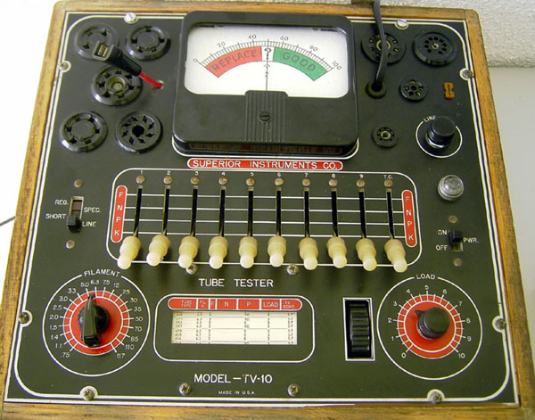
The wood sure needs a new paint, but it has no scratches or any damage. The lid can be removed, and is not pictured here, but belongs with it. The tester can test Octal, Noval, 7 pin miniature, subminiature tubes ( small brown socket on the right), Loctal, UX4, UX5, UX6, and two other sockets that I don't know the name off.
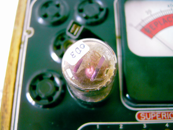
For use in Europe, I recommend to take out the middle socket on the left side, it's for USA radios, you don't need that one. Put a European side-connector in there, so you can test AD1and other l tubes from the 1940's ... 1950's. etc. Also the UX6 socket is pretty useless today, so you can put a B4 socket in there, to test RGN1064, etc. To get 4V you can take one of the strange voltages like for instance 110V, and connect that to a small transformer that gives 220 to 8V. (like a door bell transformer) Then when you switch to 110V you get 4V instead. That will give you a very nice tester. The load setting for AD1 is the same as for the 2A3. You can test almost any tube with the tester. Even voltage regulators can be tested. I tested a 150V OD3 tube in one of the next pictures. Or just use adapter sockets, and plug those into the octal socket. All materials to make those I have for you.
|
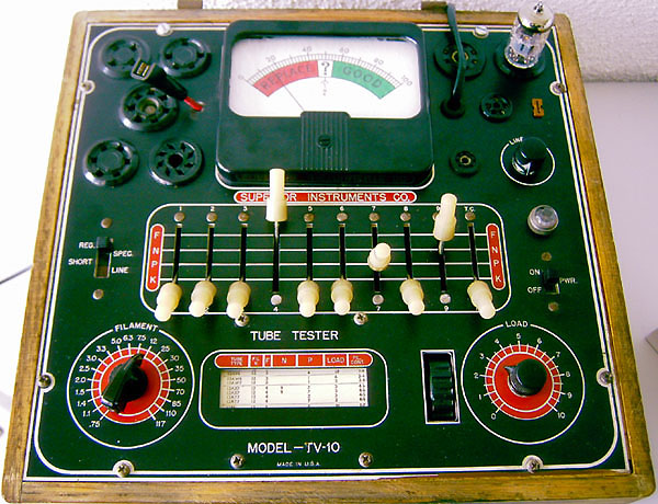
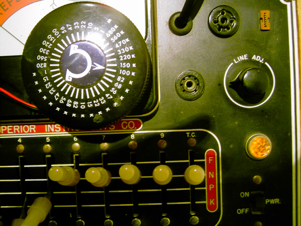
TV10. Mains voltage adjustment, works good
|
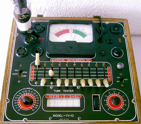
TV10. This a new TESLA E83CC, that had one bad section. The good sections tests fine on all tube testers I have, the bad sections is quite weak on all testers. What you see here is the good section
|
|
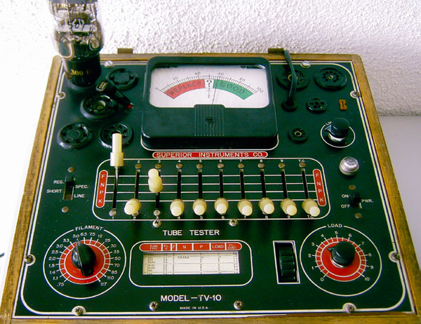
TV10. This is the same tube, the bad section. Note: You only need to flip switches 2 and 7 to test the both sections of a double triode. Very comfortable! This tester reacts quite negative on this tube. Good tester :)
|
|
TV10. This is a new production 2A3, Electro Harmonics, gold grid series.
|
|
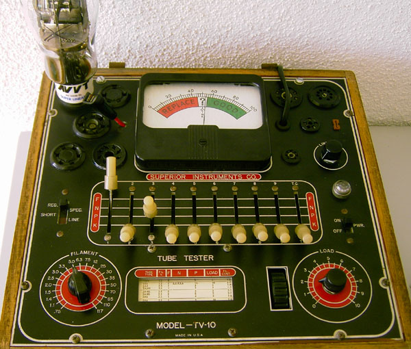
TV10. This is a used AVVT tube that was just just below ok, when I got it back. This reproduces nicely on this tester. Note you can test 300B on this tester too, though it is not on the roll chart, because it didn't exist when this tester was made. For 300B use 2A3 setting, but take 5V filament. Any later tube, 6550, or KT88 is no problem to test, take 6L6 settings.
|
|
A new, good Emission Labs 300B.
|
|
TV10. This is a weak, suspicious Type 50. This tester has the funny 7.5 Volts filament voltage for it!
|
|
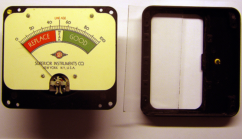
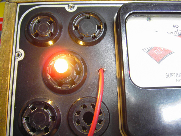
TV10. When you test a voltage regulator, this will light up the tube, when it is good. The needle reading should be only four lines.
|
|
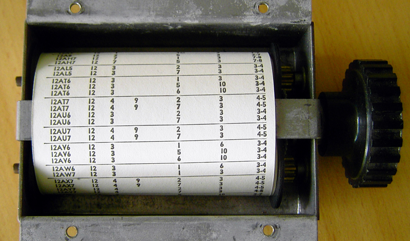
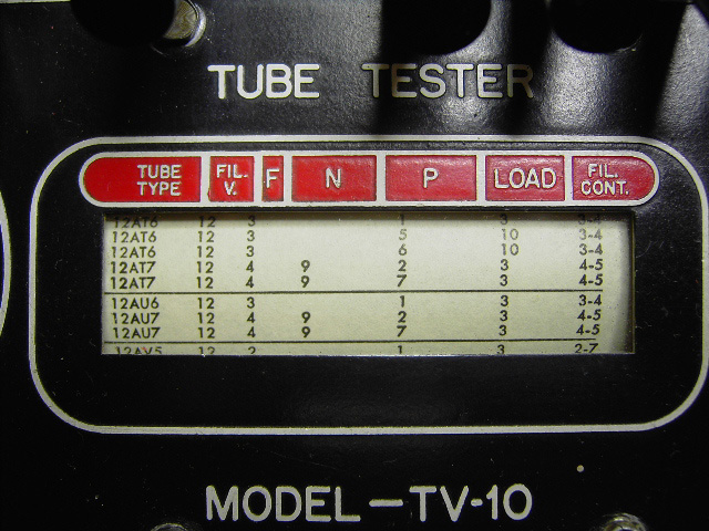
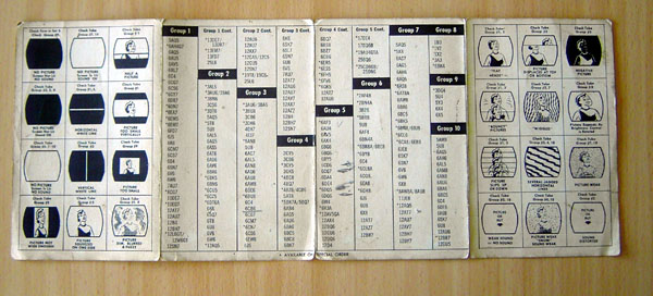
TV10. This tester has a LIKE NEW Roll Chart. You can see it is an almost unused tester
|
|
|
TV10. This is how to test the leakage function of a tube tester, you connect a variable resistor, to random pins, and then try to find the "leakage". The lamp should start to burn at around 1Meg ohms, be 25% brightness at 400k Ohms, and be nice bright at 100k. It works perfect with this tester.
|
|
| TV10. This is the leakage test, from plate to cathode, with the 807 tube. The lamp burns very dim, which shows some leakage, but this is a good tube, as long as the lamp burns very dim. It says so also in the manual, so this tube is ok. |
TV10. Perhaps not so important today any more, but still very handy. In the middle of this socket is a connector where you can press in a scale lamp and test it on any of the filament voltages this tester has. ( and that are many)
|
|
|
Attention: This tester is modified for 230 Volts!
|
This was with it too
|
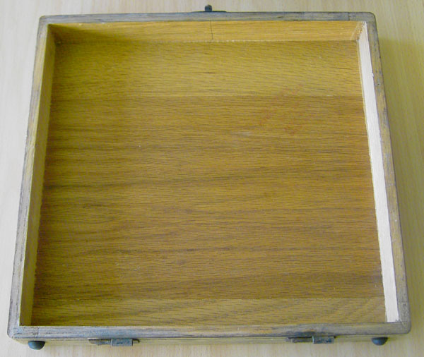
Oak wood case
|
|
Calibration and repair.
I am send often technical questions from people using the TV10 or TV11, based on my recommendation here. It has been some 10 years ago when I had this TV10, so I am doing this from memory.
So far, TV10 was the only one fo those "simple" testers that
really picked out the bad tubes. Sometimes these very old
testers do am amazing job. There may be others, but I think TV10 and TV11 are both like
that.
(Also the Grundig "TUBATEST" is like that. There is one with and one without the tube sockets extender, if you want to use a tubatest, better buy the one that has a unit attached to it, with all sockets, like Octal sockets)
For repair, I recommend you to go this way:
-
Send me high quality pictures of the inside if you want. I might
see what you don't see. Also you need to that anyway before
you begin.
-
TV10 is just the tube rectifier version of TV11.
You may have a bad acorn tube in there. The tube is very small, and has no socket. You may not recognize it as a tube at first. You can't replace this rectifier tube
it by anything else, as the roll chart settings are usually
based on the internal rectifier. You do need to find out if the acorn tube is good. Ideally with
another tube tester, but when you don't have one, you should take
it out of the tester, and verify it on the bench, by checking the forward
voltage against the data sheet. For this, remove it, so
you can nicely see what you are doing. Then, glow the heater wire with an external transformer. The
one from the TV10 is connected to the mains, because the
inside transformer is only an auto transformer. So I wouldn't
use the internal transformer for that. When you have
the heater glowing, there is a cathode and an anode of a
working diode. You need to flow some DC current through this diode, simply
with an adjustable DC power supply directly to the diode. I don't know the tube tube, but you need to verify it against the
data sheet. (not against what I think here....)
But for instance at 20 Volt forward voltage at 20mA the tube is
probably good. You really MUST take this from a datasheet, or
use another tube tester. Simply replace it with a tube from Ebay or so, is unreliable,
it may be a bad one as well from too long storage, and on Ebay
lots of crap is sold. So one way or another you have to test it.
I could test mine on another tube tester.
-
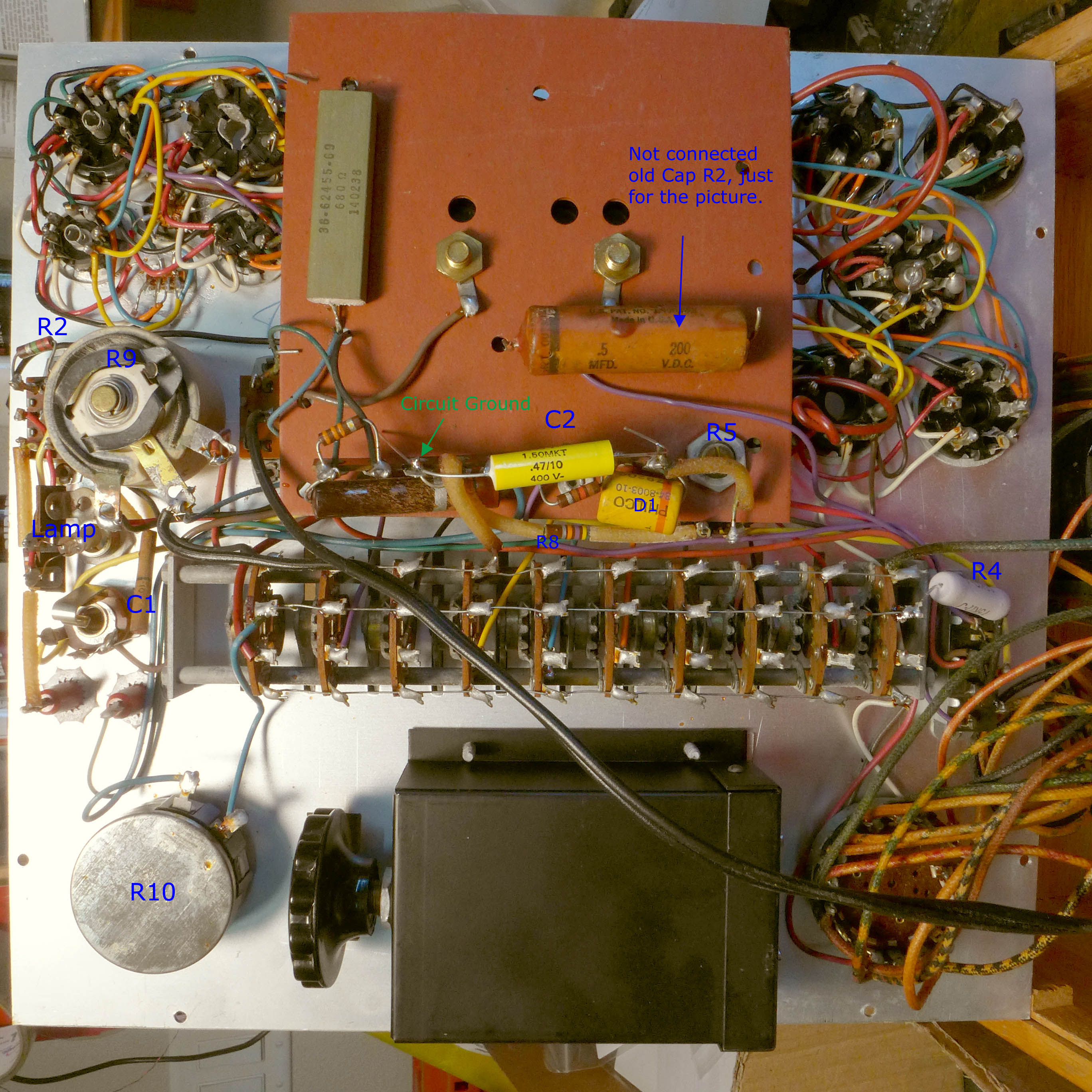
Resistors: In my TV10 all parts were still ok, but when some resistors are
off value, the whole rest is suspicious too. These are carbon powder compound resistors, so just carbon powder baked into something like resin or clay, or whatever it was. This compound was in contact with air and humidity all those 60...70 years, and resistance has gone up, also contact to wire ends can change any time once you begin to use them after 40 years of storage. Specially when you soldered the wires, these resistors are junk, as the compound is brittle and will crack. So replace them, without further thinking.
-
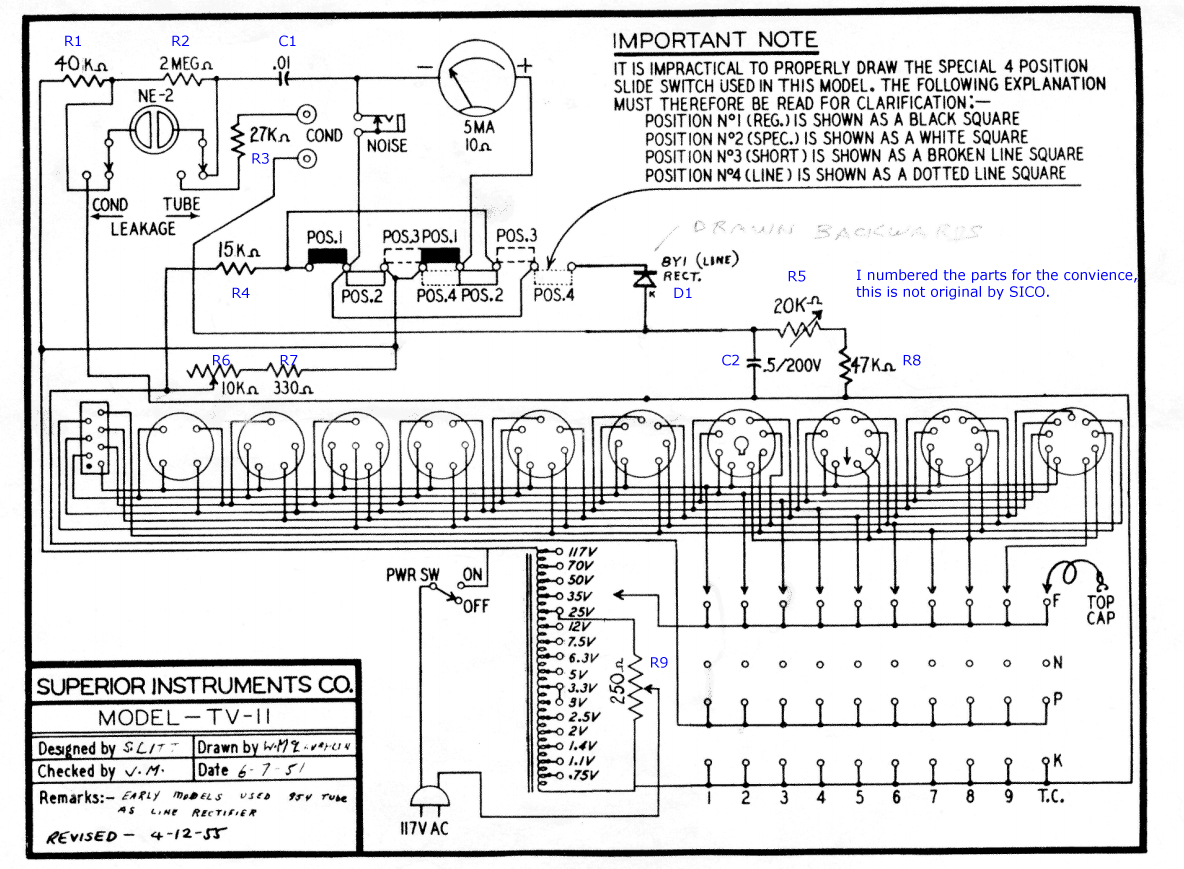
Capacitors: These are always bad. Best is take a foil type also for the 5uF one you see in the schematic. They're more precise than electrolytics, as those which are - 30% or +100% sometimes, and foil caps are 3% or so.
-
Check the potmeters too! Take them apart if needed.
-
After put it back together again, it should basically work right away, with so few parts inside.
-
For calibration, the calibration pot meter is
the one that is not accessible from the outside. This needs to be set
such that the mains calibration mark is the center, BUT..... nobody
can tell you at what condition to set it. If somebody knows, please write me, so I can add it here. With the Hickoks I believe that is 94 Volts at the internal transformer. (So after the series resistor).
So the series resistor is set such that you have 94 Volts across the
transformer, regardless the mains voltage. So that would be for the lowest possible mains voltage in the days of 110V. I assume something similar
with the TV10, but not really assume this is 94 Volts. It can be another voltage. I can't really help you much here, so think for yourself, and do not blindly do as I write here.
-
The problem is, the internal calibration is important, and I have no
reference for you how to set it. In the end, you may have to set it
by trial and error, and that works pretty good actually with such a tester like TV10. In that case I recommend to take the AC voltage
directly across the transformer as a reference. If you have a
known to be weak EL34 for instance, and the tester says it's fine, you need to re calibrate the TV10.
Then you change the mains voltage know somewhat, until the tester
begins to indicate a "weak tube". Then you let that as is, and
re-adjust the calibration mark on the panel meter. You need
to do this with some collection of tubes of course. Not just
one tube. However you need really tubes that you know are weak. So any random tubes will only confuse you. So when the tubes in your box of "weak tubes" are indicated "weak"
and the tubes in your box of "strong tubes" are indicated "strong",
the tester is calibrated right. Logically you can now take any
unknown tube, and find out it's condition.
-
It is a good idea to check the panel meter, it should read 5mA full scale. Also check it's linearity. Issue with panel meters are quite common, though this one here is 5mA, so it is a rugged version.
-
You may want to protect the meter with a parallel capacitor. Mind the polarity! It's a good value, when this visually slows down the meter. I do this with all my tube testers. It's a too big value, when the meter goes into negative before going to zero. That's just unusual to see, but not a problem, it's a charge-discharge effect where meter needle energy charges the capacitor, and then the coil resistance drains it again, but that gives negative current. Some small negative overshoot is ok, and not even all meters or testers do that. When the needle moves a lot slower, the cap is fine, and it doesn't influence the measurement, as this panel meter (moving coil) is an averaging type always.
-
Check the leakage neon lamp by using an external 2 Meg pot meter and connect it between grid and anode of the UX socket, while set it for a 2A3 tube, but put no tube inside. At values of appr 300k...400k the neon lamp should begin to burn. If that value is totally another, you have to find out why. This is determined by the 2Megs resistor on the schematic. If the lamp already burns much below 400k, and the 2Meg resistor is good, the problem is NOT this resistor. The problem is another, like socket leakage from coffee drops on the flying lead sockets. Or somebody cleaned the tester deck with water or fluid, to make it look nice for Ebay, but dirt went into the flying lead sockets. These are not water proof, or solvent proof, there can be some strange "glue" like compound inside. If you suspect a problem here, just measure form pin to pin, using the octal socket, with a good ohms meter. So 1 to 1, 1 to 2, 1 to 3, etc. Then 2 to 2, 3 to 3, etc. So lots of possibilities for a leak, and you have to check them all.
-
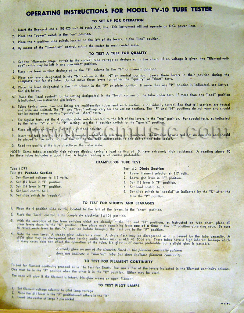
In the manual, there are several tests described and ways how to use it. Like how to test light bulbs, and how to test capacitors for leakage. It is a good idea to go all through all procedures at least once. Some problems with a leaky or bad switch, may pop up here as well, so you know what to look at. TV10 is simple of course, but problems are not there where you expect them. This systematic checking of EVERYTHING, makes you find faults with instruments in general.
-
Heater voltage: You may want to check what the heater voltage of a 5U4G is doing. I would expect the 5V to be like 5.5V unloaded, and drop quite below 5V with the tube inserted. Then, with the mains adjustment knob, you should at least be able to get it back to 5V. So that is actually two settings of the mains knob. You may want to check what the main calibration mark is saying with these options. That gives you some idea what the mains calibration mark is for, and perhaps also if it is set right or wrong, internally. Though better for re-calibration is looking at what a known to be bad tube is doing. And not so much heater voltage. Take good note, heater voltage is often wrong in tube testers on purpose, or it was just a way to work with cheap transformers, but in such cases, the tester's settings compensate for this. Specially for very powerful tubes like 2A3 that is even a good way. So this little tester can not load that tube with 15 Watt, but it can do with less, and do so at reduced heater voltage, which takes place automatically with 2A3. So I just write this here, in fact to tell you, to look not so much at the heater voltage. It is sometimes "not right" and yet this was intended.
QUESTION.... If you found a better calibration procedure, please let me know.
I will be glad to place it here. It is interesting to see, so many people use this tester.
|