Kalibr Tube tester L3-3 Main Page
CONTENTS
- History of the Kalibr Company
- Technical Specifications L3-3
- Versions of L3-3
- NOS L3-3 Testers
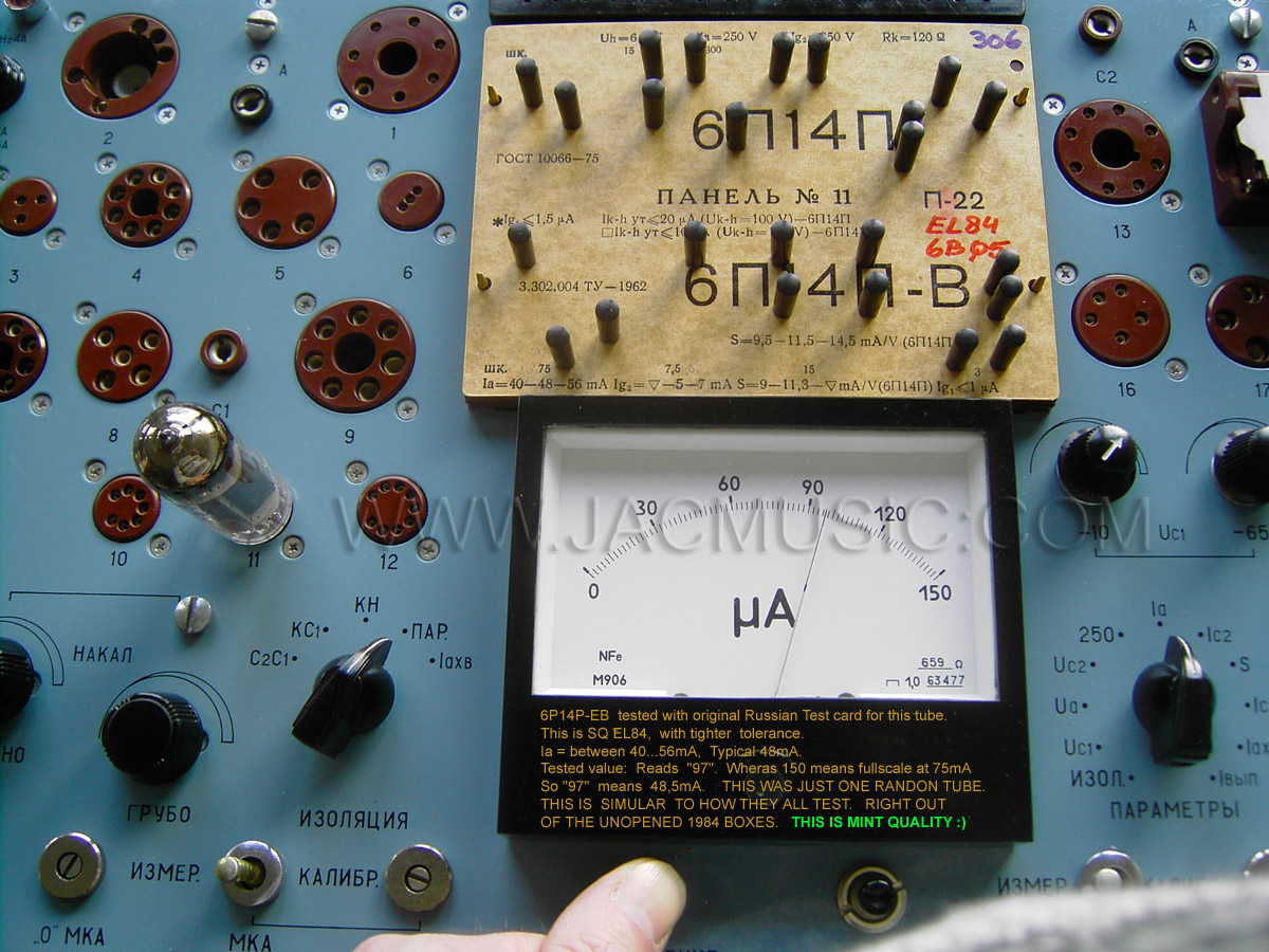
- Test cards.
- Cards Box
- Translations of the manuals
- Gas filled Voltage references. Back to the roots
- Burn-in fixture for double triodes
- A Triple Scale Meter
- A Computer Interface for my L3-3
- A fantastic test report by my friend Marc Michalzik
- A brilliant Modification by Anton van den Oever
- About the transconductance test method, by my friend Wolfgang Trinks
- Improvements and modifications.
- Calibration
- Ebay problems. Here we go again
History of the Kalibr company
Kalibr was a manufacturer of military radio communication equipment. As the cold war ended, in 1988, they had to move away from making weapons. From the old website I read between the limes, they had great problems with that. They write that after 1992 their product line was expanded with elevator systems, which became their dominant business. But I also read confusing information about restructuring, privatization, and how they are offering office space for rent. It ended with a closure in 2016.
This how to find the old address in Google Earth: Минск, ул. Фабрициуса, 4. In 2016, the website kalibr.com was erased, and all you can see there now, the domain is for sale.
There is however a WEBSITE COPY available here: Old website copy. Here is a picture of the old building, in which the L3-3 were build.
Today (as I write this is 2026) some remains must have survived, and while Russia and America want to make themselves great again, Kalibr is now making army supply, such as ballistic rockets.
Introduction
I bought my first L3-3 around 2010 or so, for 240 Euro, which was at the time a lot of money for such an item. Apart from the usual shipment damage they all have, if not send in a wooden crate, it was in very nice condition. The outside housing is made on thin aluminium, which deforms easily, but can also be brought back into shape with a wooden hammer. The inside chassis however if it damaged, is hard to repair.
I like to say sometimes, the L3-3 has no design mistakes. This is not 100% true, but almost. It was made with the best components of it's time. I never heard something about hidden errors, and the circuit amazes me with it's cleverness. The only things to take care about, are small items. The only weakness I see, is the general use of carbon potentiometers which are not very temperature stabile, and the use of Zener diodes for the internal reference voltages. There are four inside, -200V,- 100V, +100V and +250V. There are important for keeping the calibration stabile. The tester works fine as as it is, and most users will not even notice. There is however a way to improve this, and you can lift the L3-3 to a higher level, as intended by it's makers. This is why we should not call this an error.
A specialty of the L3-3 is the electronic nano ampere meter for the very low current measurement. This offers a 0,75mA full scale on the meter, which means 5nA per division. This electronic meter is also used for leakage current and grid current.
My first L3-3, as I received it. What a beautiful machine!
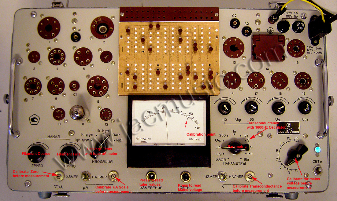
Explanation of the front plate

A similar one, but this one is modified with all upgrades, apart from the computer interface. (D-Connector already mounted)
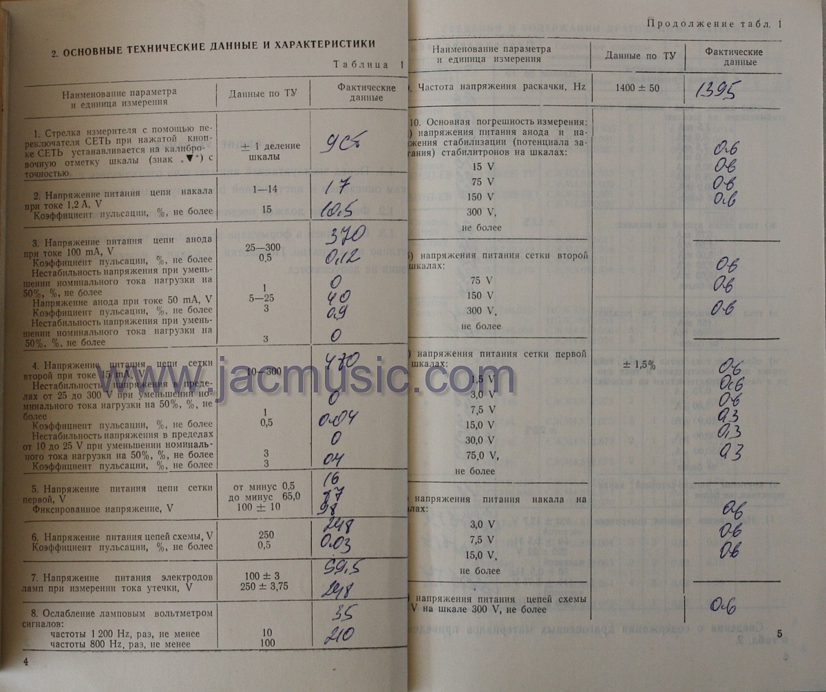
Technical Specifications L3-3
incomplete.
Anode Voltage:
DC:
5...25V 50mA, 25....300V 100ma
AC: 350-0-350V, 450-0-450V, 500-0-500V.
Unspecified:
Anode Voltage can be adjusted above 300V, when using an external voltmeter. It seems possible to adjust up to 450V, at 25mA. At higher current, the voltage must be reduced, until 300V, 100mA (specified) is reached. It is recommended to do this only very short, as this may heat up the regulator tubes beyond intended level. Yet at low current, this seems well possible to do.
Screen Grid: 10...300V 15mA
Control Grid: -0.5 .... -65V.
Heater Voltage:
DC: 1...14V max 1.2A
AC 2.5, 3.5, 4.5, 5.5, 7V, max 3A
AC 10, 13V, max 1.7A
AC 15, 25V max 1.2A
All DC voltages, apart from DC heater, are stabilized.
Additional Voltage for some tubes: +100V fixed
Leakage:
Heater- cathode: Test at -100V or -250V
Leakage current:
with electronic nano Ampere meter.
Transconductance:
Full scale of 1.5, 3, 7.5, 15, 30, 75 mA/V. Tested at 1400 Hz. Tube hum, and signal distortion (curve unlinearity) are filtered out by extremely sharp notch filter. This results is true and real Gm measurement. So any artificial, too high Gm, due to tube hum and distortion is impossible.
Gm measurement can be calibrated before use, with internal reference signal.
Auto Bias Resistors:
30, 50, 68, 75, 80, 100, 120, 150, 160, 200, 400, 500, 600 Ohms
Maximum use time at full power: 2 hours.
Heat up time for stabile operation: 30 minutes
Precision: Maximum 1.5% error
Power consumption: Max 300Watt
Mains Voltage : 127 +/- 12.7V or 220 +/-22V.
Mains Voltage Calibration: With build in auto transformer.
Working Temperature range: -10 ...40°C
Reliability: MTBF 1250h
Weight: 22kg (Bare tester).
Accessories: Spare fuses, Spare tubes, Anode Cables and capacitor adapters, Universal Card, Test cards in green box. Wooden shipment crate
Versions of L3-3
I do not recommend any other model than L3-3. Models like L3-1, L1 etc are a lot older, have tube rectifiers inside, the electronics get much warmer, components inside are 20 years older, and have seen a lot more use. The electronic components of the L3-3 are from the late 80's and good material was available at that time. I cannot say this from the 1960's.
Some versions of L3-3 exist. Though they seem to work the same, the complicated switch to select the parameters, does not have to same number of decks inside each tester. There can be differences in the look and the feel of the switches, color, and a few more details. There is one with a more modern looking meter, and one with an older type meter which looks more rounded. Though I would say both meters are nice. Also different language versions exist, though 99% have Russian text. The one pictured above here, I like it most, it has nicer feeling potentiometers for the heater voltage, the fuses are on the right side (vs left side with other versions) and this one has 'A1' and 'A2' vs just two 'A' plugs.
This is another version, with blue deck, and some small differences in placing of heater potentiometers, and banana plug designations. Don't pay too much attention to that, differences are small. I think you can recognise it by the paint color, blue or grey. It is just I want to point this out here. Even people using L1-3, so the previous model, with tube rectifiers inside, see no difference in using it, or in appearance.
There are also different versions of the panel meter. The ones pictured here are the newer, square meters. The older meters have a more rounded appearance, and these are just as good. Even so, the newer meters have a plastic insert, which likes to become darker or yellowish. This can be cleaned, but the older style meters (not pictured) don't have that plastic insert.
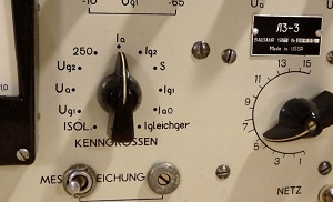
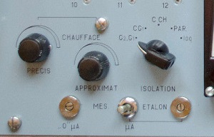
Very rare versions exist with a German, or French text deck.
NOS TESTERS
What to do: BEFORE first switch on
Real NOS means: Stocked ever since and never used. In case you can buy such a tester, be aware such long storage is not good for components and isolation materials. Often, testers pop up, which have never been switched on for years. Most of the time, someone switches it on, to see if it is broken. When it works they feel great about it. Sadly, this does avoidable damage to the electrolytic capacitors. Damage of a kind, which becomes a problem later, and the famous recapping has to be done. People always feel great about recapping and post proud pictures of it. But you replace the original military capacitors by lower grade parts, and after 10 years you have used "made in China" stuff inside. I think your are better off with the original capacitors, if they are still good. I replace only capacitors which are out of specification.
Here is what to take care off.
High Voltage power supply capacitors need to be formed ALLWAYS after storage of more than 5...10 years. You can discuss about 5 or 10 years, but not about 30 years. That NEEDS a forming procedure. If you don't do that, you will violently form the capacitors. This will give burn spots inside, and these are the beginning of later problems. The original caps are top quality. For forming, you need to solder one wire off, and slowly charge them via a 1 Meg resistor to it's rated voltage, or higher if they take it up 10% more. You will see then, voltage goes up quite slowly. Same as when charging a battery. Like a 350V capacitor will accept only 80Volt, and then rise slowly while you watch it . So you see 80V...82... 84... 86V Etc., until the maximum as written on the cap. That can take while! Then if you can go just above maximum, they are fine. After this, like when you re try the next day, you will see they accept immediately 350V. This is now a formed cap. This effect stays for many years in storage.
Once you saw the above, you will understand what forming is, and why it hurts to hit them with 350V right away after 30 years.
Here comes an interesting thing, If you find they are all formed already. It means the machine was switched on already by someone. So hopefully professionally formed, but better not count on it. If a capacitor has something like a voltage limiting effect BELOW the voltage that is printed on it, and if you cannot form it any higher, this means the capacitor is defective. Please google a little bit for this item. Some make a art from it, to repair bad caps this way. That is a bit extreme. I would rather replace a bad cap. The other extreme is, to fully ignore this subject, just switch on the tester after 30 years, hurt all caps, later not understand what causes specific problems, and blame it on the 'old stuff' instead of on yourself. Using a Variac instead of professional forming is not the best way, but a lot better than simply switch it on.
Still keep in mind, 30 years is a long time. Better form the correct way, and the old caps can all stay in and they all stay good for some more decades.
 After all HV caps are formed, you should leave the tester switched on without card for 24 hours, and watch it. So not leave it on over night. You can never say what it will do. Then after 24 run hours, use some card for a pentode, but insert no tube and leave it on like that for 1 week. This is a long time, but this is actually recommended in the original manual, and I agree with this. This will internally dry the transformer, and all foil caps too. After this time is over, you will find many things stabile, that were instable before.
Some maintenance is a 'must'. Like replace the Grid Voltage Pot meters, these are terrible quality. Look here at improvements for other recommendations.
Test Cards
 The original card set with the L3-3 is very poor, it is mainly for Russian military tubes. I tried to make some test cards myself, and soon found out, you can do many things wrong. Then I tried a freeware program that was around for making test cards, but soon I found out, this program makes mistakes as well, and it burned out some resistors of my L3-3. Luckily it was easy to repair, but I learned this program was no good. So those free cards, I gave up on those. The problem is, most cards work, and then unexpectedly a card is bad, and smoke comes out of the tester.
Free test cards
In the internet, I have also seen cards, made by using a graphics programs like SPLAN. I damaged an expensive NOS RGN1064 with it, and I guess I was lucky the tester survived the fireworks. Also there is a card printing program around, which by itself is very nice, but unfortunately like the author writes, the program can and will have failures. I thought it was perhaps a small bug or so, but these program errors also connected some illegal points inside the tester which caused a heavy smoking short. After that, I was cured from free cards. Though it worked for 15 or so tubes initially, this was not worth it for me. Information junkies are spreading this still in the internet. Well I guess I was one of those myself. The problem is, such errors can damage the tester really unexpected. When a card has an error, it is really possible you switch on the tester, and the same moment something begins to smoke. If the smoke comes from the cable tree, or a short underneath the plugs deck, it becomes hard to fix. If you short the rectifier tubes high voltage winding (1100 Volts AC with center tap....) I think the transformer is gone within seconds, as the transformer itself can do 400..500 Watt, and it gets all absorbed in one thin wire winding. So better don't use such cards. So that ended my free cards period.
Please don't misunderstand me, I recommend against the free cards in the internet, not because we sell our own cards, but because I learned myself the hard way they are a risk to use. That is why I made my own cards, with a software. On the positive side, with L3-3 it is possible to do things, which you would perhaps not expect, and expand the possibilities of the L3-3 very much by that. But, this involves good understanding of the schematic, about tubes, and about testing in general.
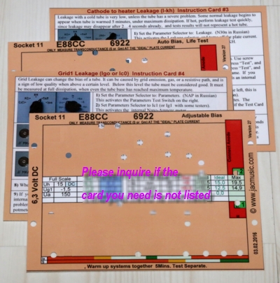
Just to give an example, I have special cards, using an external bias resistor, connected to one of the sockets, which has pin holes which fit normal banana cables. It works as simple as that. These are to simulate a SE tube stage, using the L3-3 as power supply. You just need to have the idea, and find out via the schematic, if and how this can be connected. Originally, we sold single cards for 5 Euro, but this is too complicated for buyer and seller. Also people that need many cards, pay too much like this. We offer now all cards together on a CD. You need to print it yourself, and before going through the work of making a nice punch hole card on hard paper, or photo paper, you can first test the cards of your choice, by printing them on office paper. In that case, just pick the plugs through the paper. On the CD is two addresses of companies who make a nice hand hold hole cutter tool.The cards are continuously improved, in terms of tube data, setting methods, and convenient use. Many improvement hints came from buyers. Also questions for new cards, may be answered positive, for buyers of the CD.
We also have a card which uses the tester as a lab power supply, which is so obvious to do, because it has all voltages for a tube circuit, including the heater.
Test Cards. Programmable hardware can not better than it's software!
 Apart from the classical way to set the control knobs, and read the result, which those new cards of course also allow, it gives in addition also "quick settings". Like when you need to set the grid voltage to 5.2 Volt . This is done a 7.5Volt Full scale, on a meter with a "150" scale. That is extremely confusing, because you may need to set the Anode voltage to 135 Volts in a 300Volts full scale with the same "150" meter. Then read anode current of for instance 42mA on a 75mA full scale, on the same "150" meter for everything. If you find this confusing to read, wait until you have an L3-3. That is just as confusing. I say it often, the L3-s has no known electrical problems, but this issue with the panel meter, for me it is one, and I have solved it with better made cards.
The quick settings relate everything to a scale of "15" and there are no more calculations to do. So in this case, the card says: "10.4", your just set the reading to 104 divisions and you are done. Same for all other settings, of heater, G2, and Anode. Like this it is hard to make a mistake.
Then, to READ results, the calculation problems start again. Every reading has another full scale: 7.5. 15, 30, 150 or 300. To avoid this, all three test results. (Ia, Ig2, Gm) are read on a red-green scale, and you can see immediately if the tube is good.
With double triodes, you can flip from one system to the other, just by change one card pin. (Instead of changing the whole card) Moreover the cards give meaningful instructions, to interpret the test results.
In 2024, as I revised this text, we have now 195 cards, which are supplied all together, on DVD, or by email as a file download. In addition a pdf copy of all original factory cards is supplied with it, and a pdf copy of several handbooks and schematics we have for this tester.
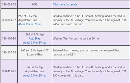
Click here, for a list of all new made cards
Cards Box
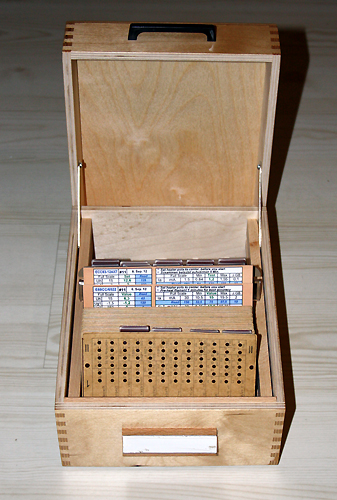
A new made card box we can supply with 3 weeks delivery time. It's not really cheap, but you it fits exactly the size of the cards, and it is exceptionally nice made.
Honestly.... The next thing missing is an English short form manual, and some solution to get English text on the deck plate.
For this, send in your meter, and you receive it back with a triple scale, in colors. (Read below for details)
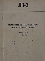
Translations of the manuals
The original manuals is in Russian only, and translations that are around are usually poor. However you hardly need the manual, when you have good test cards, and a quick set up will already work. So from there you can intuitively begin learning to use it.
There is a totally messy German translation around, but there are good versions too.
German Handbook (Improved version)
Some English manuals Exist also.
On this very large L3-3 page, I want to pay some more attention to this very nice tester. It has many advantages of a practical kind. For instance, it is very good available. Another advantage is also the good condition they usually have. Internal components are all top class military quality, and seem to survived storage and use. Once you have found the way how to operate it, and how to make cards as you need, you will see this is tester is opening new world of tube testing. The thing does what is supposed to do, with an amazing accuracy, and I can say there is no such tester available which can do all of that, for what you pay for an L3-3.
Burn in with the tester itself.
The L3-3 is ideal to burn in tubes, but only one tube at a time. please note, for safety you should always use auto bias for burn in. In tube factories they do the same, We have made many cards for this. Double triodes can be burned in both together..
Burn-in fixture for double triodes
We sell the bare PCB with cover plate, so the high voltage is mostly protected, but a protective housing you need to construct yourself. This product is well tested, but still we only guarantee the PCB quality by itself, but not how the PCB works or what you can do with it. These boards are normally on stock. Please ask when you are interested.
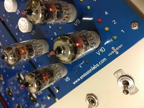
Balanced tubes
The fixture was intended for burning in 10 tubes at a time, but as a side effect it appeared we could see quickly, if each tube is nicely balanced. For this, this, just change the bias of of the whole board, and see if all triode sections respond nicely equal. This works amazingly well. The optical compare is possible, because each triode has it's own current measuring system. So immediately after switch on, you can already see which tubes are balanced and which are not. This can quickly be compared at another anode voltage too. If the tubes are good quality, initially they may be different, but hopefully they burn-in to be equal. During the process, this can be quickly observed.
Triple Scale Meter
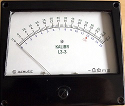 The meter has only one scale (0...150) but this also used for 0...75 and 0...30. This is such a pain, and all people use a calculator with it. I made a new meter scale for it, with all three ranges. This improves the user comfort so much. The test cards we sell, can be used with the normal '150' meter of course, but they become even more comfortable if you use the new meter scale. Reason is, settings are difficult sometimes when using others than the 150 scale. For instance how to set 47Volts at 75V Full Scale needs a calculator. You need to calculate: 150/75 =2 and then 47 * 2 = 94. It gets even harder when you want to read something, because you are constantly calculating. So when you reed 92.5 on the 150 scale, it means 46.3. Quite nasty. And then you read 93,7 meaning 46,9, and 88,9 meaning 44,5 and... actually this drives me crazy.
Now with the new made test cards, we give you this classical setting (so 47V at the150V scale) so you can use the original meter scale if course. Also, we give the position at the '15' scale. In this example it simply means set it at 9,4 of the '15' scale and you're done. So for a maximum of four settings per tube, that saves a lot of trouble, and also you can make no mistakes. Additional there is a red line at '6.3', and if possible always the heater voltage is on the 15V scale. So that makes it comfortable and reliable to set any 6.3V heater tubes.
Art work / re work the meter scale
Note, with a factory production run of high precision meters, the scale is printed such that it matches the natural unlinearity of the actual movement inside. Then, at final assembly, the meter itself is adapted to point exactly at the right position of the scale, this can be done with the balancing weights on the coil, and some other tricks they have, for changing linearity of the movement system. So this is for linearity, not for full scale. (As full scale is easier to adapt)
In the end, movement system and face plate are a pair. Only like this you get a precision meter. So when we make a three scale face plate, it is not possible to make a universal face plate for all meters, because we we must preserve the original divisions. The unwanted texts are removed carefully, and then the faceplate is first prepared with transparent paint. Over this is glued a transparent foil with the triple scale, which has only the numbers. You won't recognize this as a foil. Appearance is perfect, as if it was made like this originally.
As a final step, the meter glass and inside gets a new antistatic coating, as this is often gone with older meters. Also the needle is re coated, because otherwise the needle paint or plastic inside parts can charge up statically, causing remarkable errors when you polish the glass. Some people report antistatic charge to remain inside for months, or in very dry air, the needle paint can re charge just by needle movement. So re new the coating is maintenance, and is included.
We l add a fine red hair line at 6.3 Volts at the 15V scale. This is very convenient to adjust the heater of 6.3V tubes. At the 'Calibration' point is additionally the work 'cal' now, and a small triangle. So you can't miss the calibration mark anymore.
Price is 75 Euro (+ 19% VAT for Germany) + Shipment.
Or as download link, and there are no shipment costs.
Some hints:
- If you want to go for this, short the meter from behind before shipment. This protects the movement from shocks. The L3-3 meter is very good quality, but still please use a large enough shipment box.
- In case some defects appear when we open up the meter, we inform you about it first.
A very professional test report by Marc Michalzik
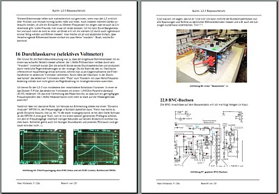 This is one of the finest reports I have ever seen, about an L3-3. Written by Marc Michalzik. It is all in German language. From a simple question about some information, developed an email friendship. Marc is someone who definitely wants to go to the bottom of things. When the explanation can't be found, where others stop, this is where Marc begins. So many, many of the unanswered questions, issues, and ideas what can be done with an L3-3, are either answered here in detail, or it is described what would be the way to go. This reports sort of opens almost the design log book of the design engineers. Marc's conclusion is, these people really knew what they were doing. Much recommended is also his edited schematic , with all functions penciled inside. This report is definitely a 'must read' when you already have an L3, or planning to buy one. Download report here.
The transconductance test method of L3-3
Placed here with friendly permission of Wolfgang Trinks. The transconductance of the L3-3 is extremely clever, as it eliminates almost all errors of the analog circuitry. This is too much to explain in a few lines here. Only thing is, it in German, but you can probably translate it in your own language if you find the right program for it.
CALIBRATION OF L3-3
 Calibration Report (small picture only).
Actually I am not so deep into this subject as the text suggest here. Calibrations is hardly needed, and the tester can be quite a lot off-calibration before you notice that at all.
The circuits design is extremely mature. Apart from the 10% type capacitors, and electrolytics in there, each single component has it's own quality grade, suited for long term problem free functioning, up to today. I found only one low quality part so far (see below under improvements) and it's not so much a bad part, but it was not over specified. The 5% caps and mica caps seem all still fine.
Make good note of this: The accuracy of this tester, is not coming from precise calibration, but from precise reference components inside. This means, the tester has quite a few calibration settings at the inside, but apart from the internal reference voltage of +250V, most of them need only to be within a certain range.
The most difficult part, where many competitive tube testers fail, is the transconductance (Gm) measurement. The worst are new made digital impulse testers, in fact curve tracers, but this is off topic here. Basically the difference lies in static or dynamic measurement of Gm. Those people who say this makes no difference, have not understood it. The Kalibr uses a dynamic testing of the transconductance. There any many misunderstandings, saying static and dynamic measurement is the same. This is not so! It would only be the same, when the tube has zero distortion, zero noise, and zero hum. In real life, all tubes have of course distortion and hum and noise, which makes the Gm look higher as it really it is. That is because these unwanted components, are falsely interpreted as additional gain. You can take any tube, increase the grid voltage by 1/2 Volt, and look at the change in plate current. Then decrease the grid voltage by 1/2 Volt, and look at the change in plate current. again. Is the change the same? Lucky for you. Most of the time it will be different, because of non-linearity of something called tube CURVES. A dynamic measurement has the advantage to reduce this error, by working with a very small signal only. Or, even better, like Kalibr is doing, by passing the signal in addition through a band filter + amplifier. This (as proven by Fourier analysis) filters out the distortion components, and also the 50Hz components and higher harmonics of that, and practically all noise as well. The remaining result is truly only the transconductance. With some tubes is makes a small or no difference, with others it makes a large difference, mostly when the tubes get older, and linearity gets less.
The KALIBR has the option of a quick user's calibration before doing a transconductance measurement. An extremely low distortion test tone, which is produced by the machine itself, is compared with the equipment's own result, and by this, the machine will now correct it's own error. After this is done, the tube is measured with the same precision as two reference resistors which are inside, and the error of all other electronics, the tubes, etc. becomes eliminated. This method is still found in some ultimate digital multi meters that are self-calibrating. Such as the Agilent 3458A multi meters, which cost the same as a new car. It is missing in the expensive Amplitrex AT1000 digital tester, but ok that would be too much to ask for what it cost. But.... hey... the L3-3 has it :) This brings the precision in the range of less than 1%. Even so, with a lousy calibration you will get <1% error, since the reference they use is only made of only two precision resistors. Brilliant as it is, this method even compensates the error of the panel meter. So it would be a big misunderstanding that you get more precise results by an internal calibration. The L3-3 Gm test method is so extremely clever, I have never seen a tube tester doing this in a better way.
 Calibration Report (Just one page)
With a good internal calibration, the EXTERNAL calibration is done only once, and then you can measure whole series of tubes with it with a beautiful precision which is identical to the panel meter's reading. So what you read is then guaranteed what you have.
Here is a link to a Calibration procedure as used by one of our customers
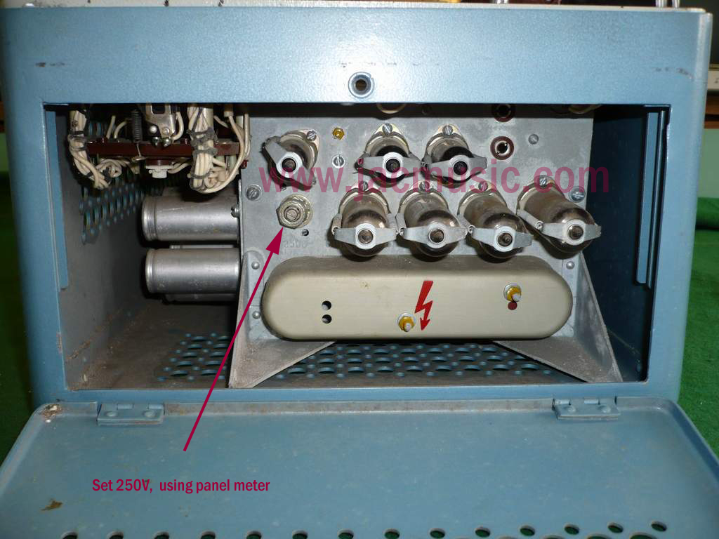 The tester has a tube regulated 250V supply voltage, which is used for the internal oscillator, the band pass filter of the transconductance test, and for the electronic nano ampere meter. Each of the three depend do not depend not so much with their function on a precise 250V, but they depend with their stability on this voltage to be THE SAME as always. The oscillator frequency, depends very critically on this 250V. The closer you are to the center of the band pass filter, the more stabile the transconductance test gets. So not more precise, but more stabile. This means you don't need to do the EXTERNAL calibration very often. So adjusting the 250V, is one of the first things that helps here. After the tester is warmed up, it must be 250V, but mainly it must be STABILE. So if it drifts, you have a hardware problem.
Mains voltage calibration.

This is a more difficult one, but important. There are some reasons why this calibration is off specs sometimes very much. (More information here) . I would recommend you to do only this work, and then observe the tester. Many times nothing else needs to be done..
I mention it here, but you should NOT touch this calibration point. The panel meter is calibrated by itself, inside the meter. Yet, the meter as such is again calibrated into the tester, to compensate for individual loss of magnetism by the mains transformer. So the meter may be 150uA by itself, but would need perhaps 153uA or so, when it is build in the tester and the lid is closed, because the mains transformer drains some of the magnetism out of the meter. This is normal. To compensate for this, there is a tiny pot meter underneath the deck. I have no idea what the calibration method for this is, and I would only say: Don't touch it. Picture1 - Picture2.
Some Improvements and Modifications.
L3-3 to my opinion has the best price performance ratio of all analog tube testers. I think it has no design mistakes. We should not really wonder, because is a an evaluated product. Yet, some improvements are always possible. |
|
How it works.L3-3 transconductance measurement |
|
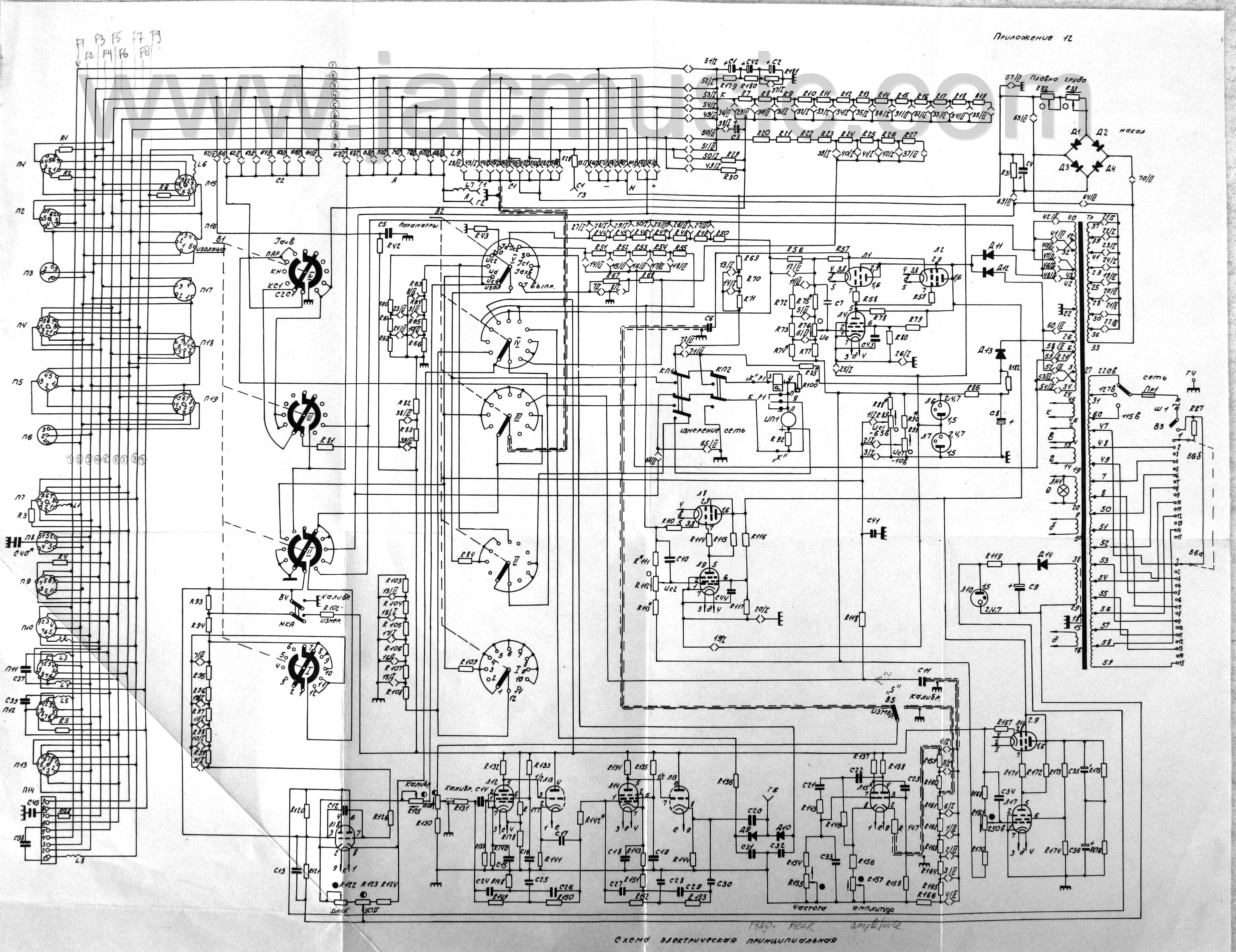 |
A schematic on loose paper |
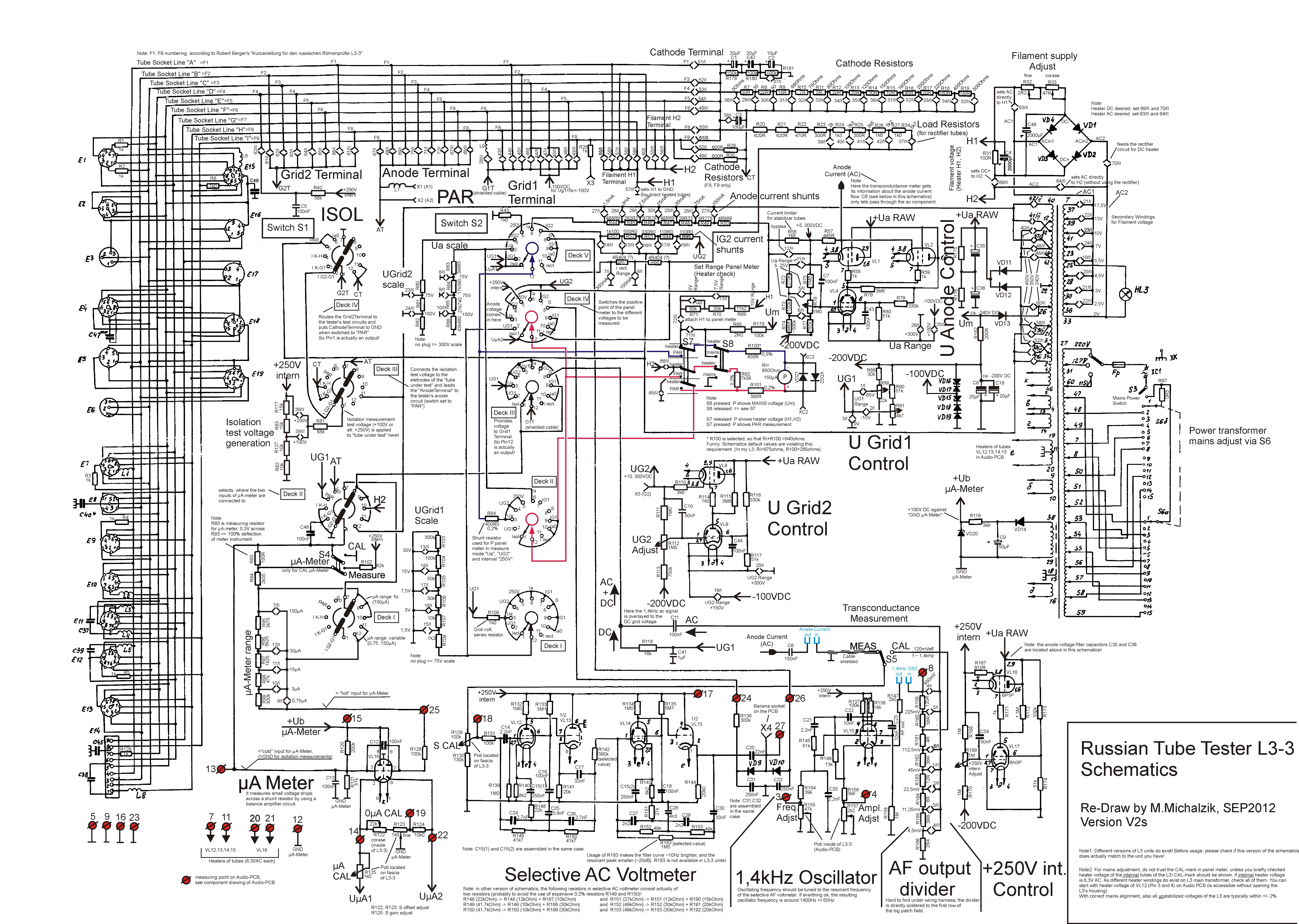 |
NEW MADE Schematic with added explanations. Schematic with kind permission from Marc Michalzik. THANK YOU MARC! |
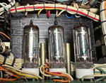 |
Internal Reference voltages improvedThe internal Reference Voltage of 250V is vital for the uA meter. Also if all (three) reference voltages are more stabile, there is less need for user calibration before a measurement. With most L3-3, the reference voltages are generated with Zener Diodes, which by nature are temperature dependant. Wolfgang Trinks found out, the 0B2 gas filled tubes of the older L1-3 are much more stabile. He replaced the L3-3 Zener diodes by 0B2 tubes, and stability improved not just a little bit, butt drastically. The oscillator is fully stabile now after 25 seconds warm up. |
|
|
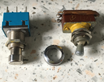
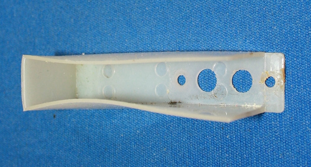
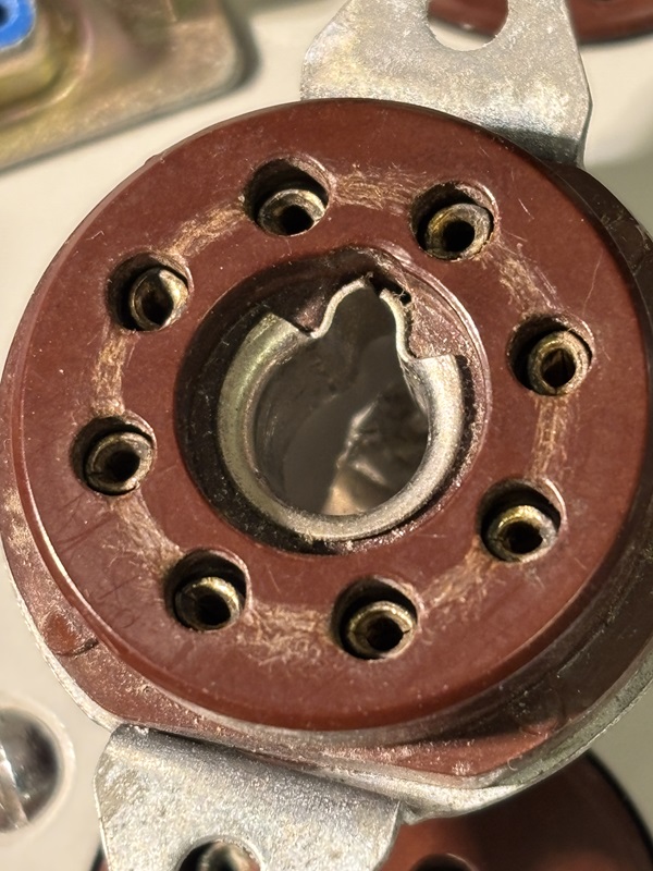
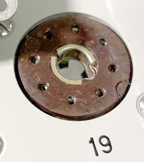
Loctal Socket replacement.It's a bit of a rare socket, but many fantastic tubes are loctal, like the expensive C3g, or the 7N7 which can replace 6SN7. I like to say, L3-3 has no design mistakes, but their loctal socket is a bit of a hack. The outside diameter is 26mm, which is very curious. It looks like specially made for L3-3, and it is not well done. The pin holes are a fraction too large diameter, so with some tubes there are bad contacts. From the two pictures, you can already see, the original socket has larger holes. Moreover, the center pin hole is too deep inside, which is very nasty. I filed off a 30mm German PREH socket, to 26 mm. So now I can test Loctal tubes without contact problems, and the center pin works with all tubes. . |
 |
Increase maximum plate current.A brilliant project by Anton van den Oever, from Hazerswoude, Netherlands.
|
|
AUDIO BOARD Overhaulnot strictly needed, but I was very happy with the result still. |
 |
AUDIO BOARD redrawn.Drawing with kind permission from Marc Michalzik.THANK YOU MARC! |
 |
Cable tree drawing from the manual. |
 |
Add a computer interface to my L3-3This project is progressing well now. This makes all data of the L3-3 visible on my PC screen. |
 |
Add Socket for Au8 socket tubes.This socket (AU8) is missing painfully. A huge variety of Audio tubes was designed 1930's until 1950 by Philips, TFK and Valvo. The original socket #2 is a type for some military tubes, that are not interesting to me. So I decided to remove that socket and make room for the Au8 socket. After removing the original socket, the nice surprise was, the mounting hold and screw holes EXACTLY fit a standard NOS AU8socket, and wiring is simple too. The result looks as if it was all original intended this way. |
 |
Add a meter protection capacitor. |
|
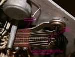
Open brain surgery at the Switch board.This tester was suffering from a nerve problem in the cable tree. At the age of 39 years, the tester needed surgery. |
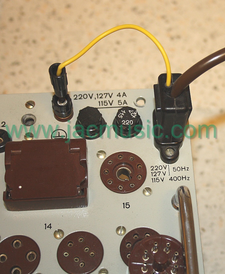 |
Detachable Ground, using the original cable. |
 |
Original Banana Socket are BAD.This is the only repair, you MUST do on any L3-3 right away, and not wait until you damage something. In the tester deck, you have five banana plugs. Two for the Anode, two for the grid, and one for ground. These are definitely unreliable, and should be replaced with any tester. They can easily cause damage with the tubes, or with the tester itself. Even so, the L3-3 that needed this repair, I bought it with a (nicely hidden...) cable tree burn damage. So it is possible, this defect caused the cable burn in the first place. All I can say, spend 2x 50 cents for this repair, and prevent big trouble. |
 |
Switch Project #1. Isolate the mains switchesWhen you plan to work at the inside for more than one time, this should be your #1 project. This costs very little work, and saves a lot a problems. When you lift the deck, even when the mains is off, you can still get 240V on your fingers, and drop the tester sure. Just two cents of shrink sleeve will do the job. |
 |
Switch Project #2. The Calibration SwitchesThese are in the deck of the tester, and need to be used prior to any measurement. If you ever had the uA Calibration Switch in the "Calibration" position, and try to do a normal measurement, you will see the whole tester is not working, and there is no clue whatsoever why that is. That was the moment, I thought a push button at that position would be a LOT better. More about it here. |
 |
Switch Project #3. Reverse the 'test' button.Normally, to see the test result, you need to press the 'test' button always. If not pressed it shows the heater voltage. I don't know how your thumb is doing, but mine starts to hurt, after testing many tubes. With a careful modification of the 'test' button switch, these functions can be reversed, and the user's comfort increases a lot. After the modification the tester indicates the test values by default, and when you press the button, it shows the heater voltage. |
 |
Switch Project #4. Dirty contacts of the 'test' button?Well that is what I thought. But no.... it was something weird. Check this, if the main 'test' button under the panel meter seems to have bad contacts, it may as well be the plastic part around it, has deformed. I decided the switch had to be taken apart, and the l first thing that became visible was the defective plastic cover. I did not expect that! This caused all that trouble since years. The contacts could not move freely inside. I repaired the thing with hot air. I also took the chance to reverse the switch for this L3-3 too (see above). |
Also one of big the capacitors. You don't expect it, but this ONE IS WITH NEGATIVE VOLTAGE ON THE CASE. Also the mains plug contacts need to be isolated. Otherwise you switch the tester off, but there is still voltage on those contacts. These pictures here speak for itself. |
|
 |
Change the Ug1 (grid) potentiometers to a 10 turns type.This is a must. Now, adjustment is done much easier. You may not have expected this, but temperature drift of the original pot meters is really terrible. |
|
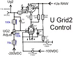
Change the Ug2 (grid) potentiometers to a 10 turns type.This is a very useful modification, because Ug2 (and also Ua) are producing the voltage from a voltage called Ua-Raw, and this is almost 600V unstabilized. Quite a challenge to make 12 Volt from this but it works even very nice. Only the set knobs react very sensitive, despite the two ranges. This modification can be done in just 15 minutes, accessibility is very good, and you can not do much wrong. Make sure you use 3Watt resistors, because the G2 line is also used for rectifier anode2 with some of the rectifier cards. In that case there can be 550VAC where it says G2. Since the selector plugs for 150V and 300V are not inserted, the G2 circuit is floating, and it is possible to apply 550V AC on G2. Yet in that case there is 700V RMS across the ladder, so 1.8 Watt. So appr 0.6 Watt per resistor, the potmeter included. So if the resistors are too small power, they might get too hot while rectifier testing. The stabilizer circuit has 150V and 300V. With the 10-turns potmeter, adjustment becomes a lot more pleasant. However there is a 1 Meg potmeter in there, and such do not exist as 10 turns potmeter. The highest I found is 100k. This value of 100k can be used, if the other values of the ladder will get 10x lower values also. It worked instantly and very good. I have dipped the 10 turns potentiometer in hot Vaseline, and afterwards let it drip out. There was so a lot of vase line inside, it turns heavier. This is needed because otherwise the knobs go too light, and you can change the setting too easily by mistake. |
|
Change the Anode potmeter to a 10 turns type.This one is more difficult, because it includes 6 resistors, and one writes 'selected' in the data sheet. More about this later. |
|
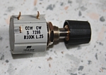
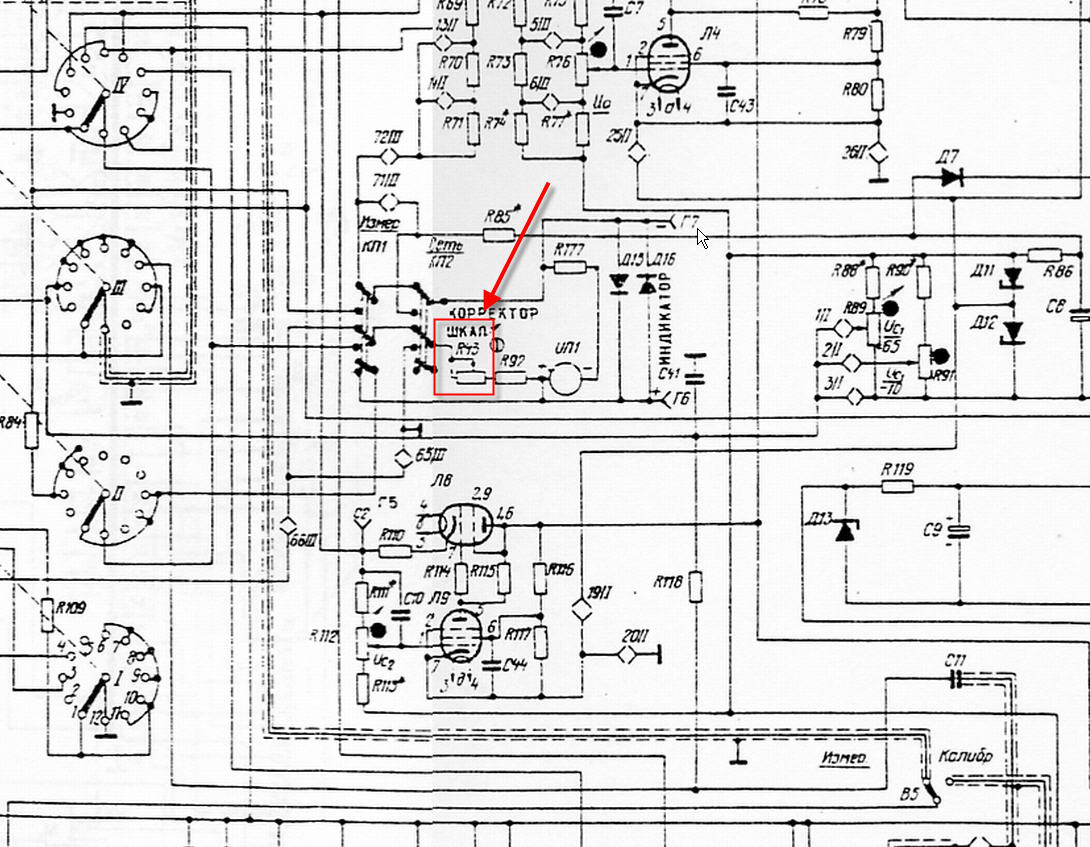
Change the Transconductance Calibration potentiometers to a 10 turns type.If you need to adjust the 'S' (=Gm) calibration before every measurement, this is kind of normal with most L3-3, but it does not have to be so. There are several improvements possible, each of them will help a little bit, and my L3-3 is fully stabile now, after it is warmed up. The original carbon potentiometer, has a lot temperature drift, and also the regulation is much to imprecise with a one-turn potentiometer. This modification will greatly improve the working comfort. |

PRICE
The market price of a good L3-3 is based on the fact that somewhere some people have an NOS stock still, and also the tester is a bit of a secret, even today. However, both things will change. So one day many will know this tester, and NOS stock will gone. It is the ever repeating NOS tune, like an LP record with a crack in it. When it's available all want to 'wait'. And when they are gone, they fight for second choice ones. This tester is many times better than the AVO Mk4. I once saw people pay a record price of 3662 Euro for a MK4, in 2010 (Auction Nr 370415230702). What a crazy world we live in. At that time you could buy a whole pile of NOS L3-3 for the same money. But I guess it's normal. It's the world of NOS materials.
What you should get.
I do not know how many of those testers are on the market, but I see several people selling really good ones. An all complete, NOS tester is theoretically the best to have, but with a clean, used one, you have perhaps a higher chance it is really good. For a NOS the price adder is appr 30%. If it is really NOS, they are fully equipped like this:
- Green wooden army crate. Inside is:
- The tester. Check if the card plugs are all with it. They are in the tester front panel, in blind holes
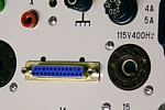
- Mains cable, with it's special chassis connector.
- Wooden accessory box , containing:
- Card set. Make sure the universal card is not missing.
- Spate tubes, complete set
- Small items, like plate capacitor cables, etc
- Paperwork three pieces, each with series number of tester on it:
- Handbook, with full construction details
- Original Schematic, printed on large sheet
- Calibration report, a small booklet for the particular tester.
- Cards. If the card set is missing, that is a real pity. The original cards for tubes like 6922 and 6SN7 are masterpieces of 'card design' and show you how to get the utmost out of your tester. (Russian designation for those tubes are another though. For instance 6SN7 is called 6H8C). Making new cards for tubes that have no original card, is DIFFICULT. This means you need to understand the tester very well. I have written a software for making cards, so it prints cards in color even. L3-3 can test almost every tube, but as said, NOT with the original card set. .
EBAY Problems. Here we go again
![]() Be careful with so called NOS testers. I bought such a tester myself, and it has a burned cable tree. Another such 'NOS' tester was sold to a certain Mr. Peter M. from the Slowakian Republic, also some very hard to repair problems which cost a lot of trouble and money. So be extremely careful, it is the same as with tubes. Such NOS 'lucky find' may as well be broken stuff, somebody put away 30 years ago. And of course the fine selling gentleman did 'not know' this. My advise is, you are much better of with a 'guaranteed good' one which is used, as with an untested NOS.
Be careful with so called NOS testers. I bought such a tester myself, and it has a burned cable tree. Another such 'NOS' tester was sold to a certain Mr. Peter M. from the Slowakian Republic, also some very hard to repair problems which cost a lot of trouble and money. So be extremely careful, it is the same as with tubes. Such NOS 'lucky find' may as well be broken stuff, somebody put away 30 years ago. And of course the fine selling gentleman did 'not know' this. My advise is, you are much better of with a 'guaranteed good' one which is used, as with an untested NOS.
Please keep the following in mind:
1) Defective ones and buying risk in general. Sometimes you see them offered as unknown condition. Remember, tube tester trouble is general is extremely difficult. Often you find the defect is a burned transformer or a damaged meter. Still, the L3-3 is much easier to repair as any other. Electronics are normal, and accessibility is a dream. The chassis has wings that you can open, and even each wire has a little plastic number tag on it, which corresponds to the schematic. In any case, finding replacement parts may be possible when you are patient. Still the difference in trouble between a really good one, and one with problems is HUGE. However, price differences for such are small. So better take a real good one, and pay a little more.
2) Shipment damage. It is almost normal, the aluminum case will deform the bottom feet in shipment when the box gets dumped. A tube tester is not a bag of old apples, but you can try to explain that to UPS. (look in youtube for 'UPS throwing'). If this damage happens, just take off the complete case with just a few screws, and you will find all inside parts are fine. Just the aluminum case bottom is deformed. It is easy to get the case bottom in shape again with a wooden hammer, but the internal frame may be damaged, and the tester will still wiggle on the desk.
3) Humidity. I do not know the reason, but many of the NOS L3-3 have been stored humid, and the inside will show some white oxide here and there. However, humidity does not seem to do any harm to the vital parts at all. Any part that would suffer, is well protected. Such as completely lacquered printed circuit boards, and the leakage switch being all ceramic.
These testers of obviously stored humid, can be very good, even though the inside piece parts seem to have an oxide layer everywhere. As far as I know, there are no parts inside that suffer from that. The critical part, the tube nano-ampere meter electronics, and oscillator are on one PCB that is dip-lacquered, and the leakage switch has ceramic decks. Such an NOS tester is more recommended than a heavy used one, since a used one is not much cheaper, but may have the typical issues any used tester has.
4) Payment conditions. Decide this for yourself. The difficulty with Paypal is, when you have the right to send back a defective tester, you still get stuck with back shipment cost, and duty if you payed some. So a large loss you have, on way or another if that happens. Do not buy it on the looks, but buy it on the good feedback of the seller.
CONCLUSION:
Amongst the top-ten testers. Best buy ever for the money.
It gets a well-deserved FIVE STARS ***** (what is this?)