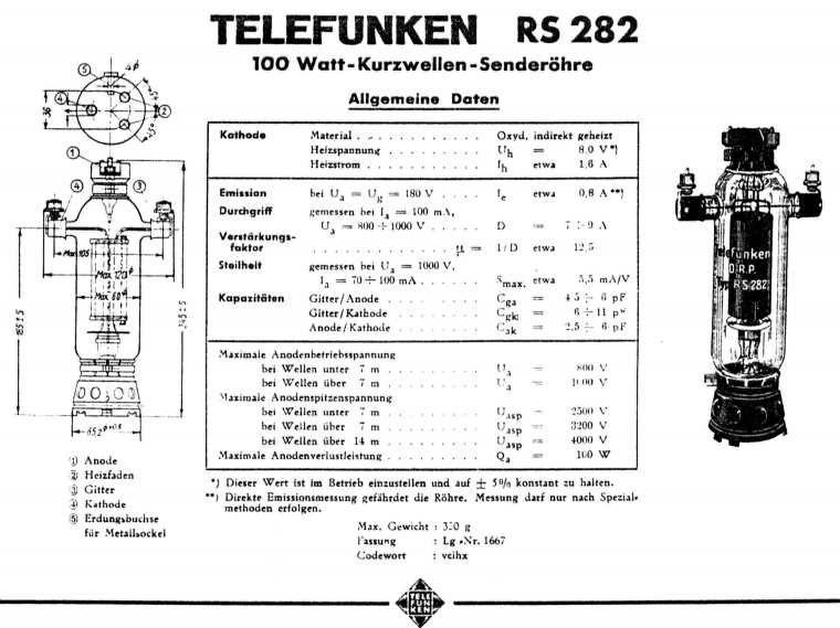
Telefunken RS282
Test card
Description
This is a 100Watt transmitter tube, Intended as a Class B RF amplifier, by the German War Navy. First introduced in 1934. It has very linear characteristics, and it can be used for Audio. However, a data sheet for Audio doesn't exist. Not even Triode curves are published. Yet this is a beautiful tube, and to my opinion a perfect HiFi tube. When looking inside the tube, you will see a Tetrode system, and it is Triode connected, directly in the tube already. The screen grid is directly attached to the Anode inside.
There are two ways to test this tubes,. and we have two cards for this:
A) Triode Mode, adjustable Bias. Test data at 300V is not specified by TFK, but sure possible. Some difficulty here is, the data sheet provides not the curves we need for this, and the (few) curves we do have are much too low resolution to extract precise data from. Test data was gathered from two like new condition RS282, on an L3-3, using this card.
B) Diode mode with all Grids to Anode. The TFK RS282 data sheet however offers a DIODE curve as well. Now this is extremely useful to test emission, and by the Funke company (check their amazing vintage testers) this is the best was to test emission anyway. So that's what this card is doing. For strapping triodes as a diode, there are actually two methods.
- When in general, a tube is not made for positive grid voltage (and current) you should not do so. With such tubes, the grid is connected to the Cathode. Diode Forward voltage is a bit high, but plate dissipation can be very high, and for testing in fact this is also good.
- Connect the grid to the anode. This is only possible when the grid is made to carry positive grid current, and when the grid can deal with the dissipation resulting from this. This will result in a vera low forward voltage diode.
Since this is a transmitter tube, 2) will apply. There is a Va = Vg curve for this diode, in the datasheet, and we can conveniently use the L3-3 for this. It should be obvious there is no transconductance test in diode mode. So this is disabled at the test card.
The socket of this tube.
There are special RS282 sockets, but HiFi builders make a construction themselves, because the tube socket uses 4mm connectors same as banana plugs.We take advantage of this. The tube is connected to the tester by banana plugs completely, also for the heater, because socket #17 of the tester can take banana plugs. Anode, Cathode, and the screen are connected by banana plugs to the tester also. Very comfortable!
This card can do following:
- Run the heater of NOS tubes first without anode voltage
- Test for Emission (with acceptance level)
- Burn in the tube. This should be done at 100...120mA to spare the L3-3. The burn in is completed, if there is no change whatsoever for minimum 30 minutes, provided the tube tests "good". Burn in is much recommended for older tubes.
Use a grid ampere meter.
Be careful not to damage the grid by too much dissipation. Maximum dissipation is 7Watt, so you will not burn the grid so easily. WIth this test, grid power is limited to appr 2 Watt. However be sure you do not make an error here, and limit the grid current to a safe 45mA, below +75V. Just put an ampere meter in the grid cable.
Oscillation
This is largely prevented by using the internal RF blocking choke inside the tester. Yet prevent funny things with too long cables. If the test set up reacts to hand-effects, when results appear unlogical, or a tube which is expected to be very good, will test very bad, in all those cases, there can be an oscillation.
Final instructions
As found on the card!