© COPYRIGHT NOTICE All Rights Reserved

Test Cards for L1 and L3 tube testers (L3-3)
(Last updated: 12-Jul-2017 9:00 )


Instruction CARD #3. Shows how to set up the tester for Heater-to-Kathode Leakage measurement.

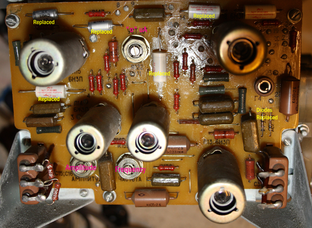
Please note this card is not hidden information that we sell, this is all from the manual. The card rather shows how to to this in an understandble fast way, and when you have not done so for a couple of months, you would not remember any more anyway. However it needs to be done each time after the teser was switched off. It is a nano-ampere meter, and it it has some offset which changes. So this card belongs together with your L3-3 test cards, regardless if original cards, or the new made cards. Dimensions are the same.

Q: What causes heater to cathode leakage?
A: With indirectly tubes, there is no cathode to heater leakage, because cathode and heater at the same things. With indirectly tubes, the Heater spiral is inside the cathode sleeve. The spiral is coated wit isolating material, which must withstand extremely high temperature. The inside heater is a lot warmer that the cathode surface itself. Many materials become slightly conductive when hot. This is normal, and we must take each tube as it is, meaning there is a data sheet value, and this the reference for that tube.

Q: What is the effect of heater to cathode leakage?
A: This causes the tube to hum. Electrically this is not very easy to understand. For this, you need to look at he heater circuit. In rare cases this voltage comes from a battery, like with battery tube radios. Yet normally a transformer is used. Unlike common belief, the hum is not so much injected via the AC wiring, radiating this into the tube in some way. Though this is the case also, this is only the smaller factor. Even when the heater circuit is DC heated, tubes can be humming via the heater wires. The reason for this is, the DC circuit is supplied via a rectifier, which is connected to the transformer still. The AC transformer winding at this place is capacitive coupled to the transformer's other windings. Between those two windings is high voltage, and this capacitance is simple there too. This capacitance should be measured at low frequency. Use 50Hz. The voltage can be measured with a very high impedance meter. So, over this capacitor can be the primary to secondary the voltage, or when it is close to high voltage output windings, voltage is a lot more. So we have a known capacitor, with a known voltage over it, and this means simply by this capacitor formula, there is a known current. This current is not "perhaps" flowing, it IS flowing, as the capacitor formula can not be neglected. The only question is: Where is it going to. The path begins at the transformer. From there it flows through the rectifier, and then via the mass of the DC stabilizer, into the tube heater, where is will find a very high resistor path to the cathode. Problems come, when this resistor is too low, and then AC current gets injected into the cathode, even when the heater circuit is perfectly stabilized with DC. For AC heating, the whole explanation is the same.

If you have problems, doing the calibration as the card instructs, it may be needed to adjust potmeter called YCT0 in this board.

However do not do so, when you can absolutely not make the adjustments as on the cards at all, so when you see unlogical things. This is an internal adjustement, and simply turn it to make unlogical this get logical, is not going to work. So in that case leave it as is. Only turn it a little bit, when you can see you need only a little bit, and when you see it helps. When you can seem to need a large adjustment, probably you make a mistake. Also make a marking with a pen before you touch the setting.


© COPYRIGHT NOTICE All Rights Reserved