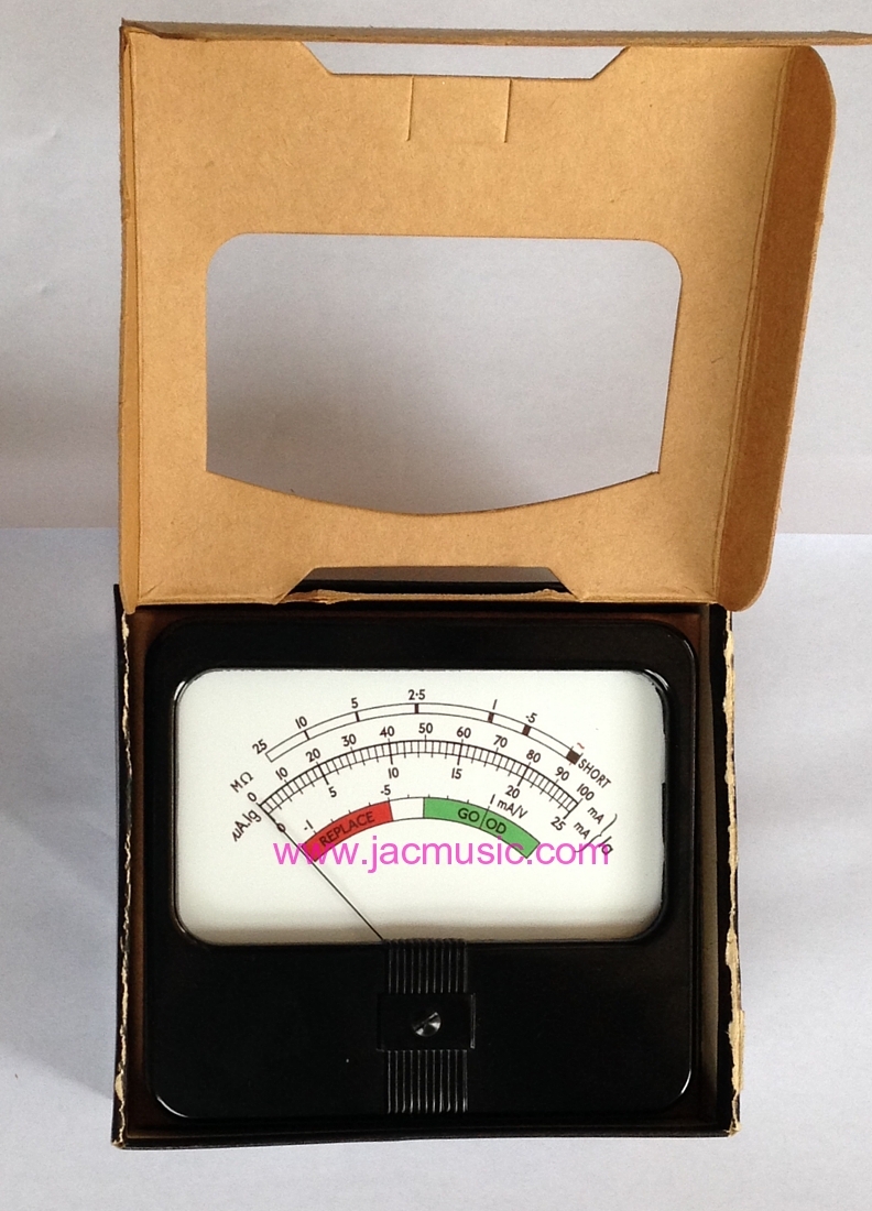
The Meter of the AVO testers.
Description
I had some questions before, and kindly answered them by email. Since the questions are often the same, I rather put the answers here.
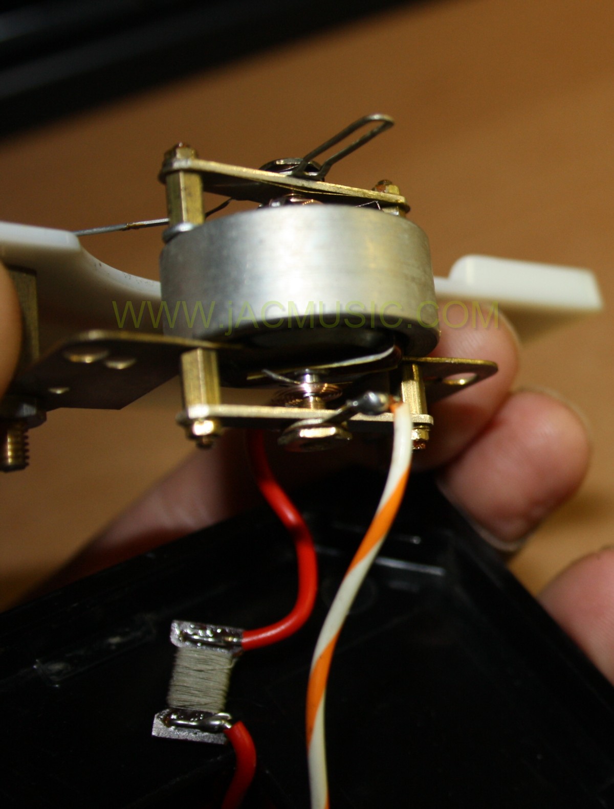
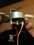
Accuracy of the tester: This depends extremely on having a good meter. You can not "calibrate away" meter errors with some other setting. In the Mk3, Mk4 and CT160 is a very delicate meter of 30uA yet at impedance of 3250 Ohms. A suspended jewel bearing is used, same as in vintage wrist watches, under various trade names. 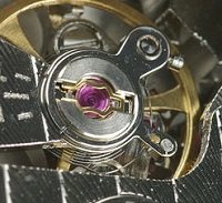 The most known is incabloc, like on the left here. In the AVO meter, you can not see the jewels, they are inside the construction. Apart from this, the construction is identical. Electrically the meter coil is made of copper wire, which has quite some temperature effect, so you need to be sure that the desired value of 3250 Ohms is measured at the standard temperature for this. There is a temperature dependent series resistor inside, but there is no specification know about this one. In the end, this cooperates temparaturewise, in the intended way, with the series resistor inside the tester, which senses the current through the tube under test. However those meters in most cases have suffered from old age, they are 60 years old, which is a bit too long to expect no problems. So often, the meters have been opened by amateurs, and when they see screws, they try to approve it by trial and error. Same for myself, but I soon found out, this doesn't work at all.
The problem is, there are no instructions, and that person probably never did it before. The result is never good, and at a minimum wrong adjustment is done, but damage often comes to it. Specially these little set screws in the middle may not be touched. There was never a bad meter, becoming good again after fiddling with those screws, but when you are done with that, you have rather an additional failure inside. Because the hairsprings need to be removed for this adjustment. Don't even think of taking off the hairsprings.
Often the meter does not look so nice inside as on the picture, but it has oxide and dust inside. Unfortunately they saved at AVO on painting the magnet. The earlier Mk1, Mk2 meters had at least a chrome plated core inside the meter coil, but the Mk3, Mk4, have only the magnetic material, whatever it is, and there is no chrome plating, and it likes to rust.
The Mk1, Mk2 meters are also sealed by the same rubber gasket which mounts the meter in the front panel. So when you see that hanging out a little bit, the meter is not (magnetic) dust proof any more. Also this gasket has become larger over time, so it is forcesd out anyway. Do not tear or break it further when it is damaged, because for repair, I re-use the old gasket. (even when cracked, this can be done)
This gasket was done better in the CT160, Mk3, Mk4, which have one gasket specially for the meter itself, which is inside. So it doesn't detoriate. The other is only to mount it, and it is not a critical one.
The moving coil of CT160, Mk3, Mk4 is very delicate. It probably happened to all of use at some point, with an operating error of the tester, to hit the needle of the tester violently in the right corner. Thinking: 'oh shit....', and then you were so lucky the meter still worked, all it needed was a zero re-adjustment. And if it didn't happen to you, it happened to the many owners before, and ever since 1958 is a long time. If the meter is damaged, typical damage is: Linearity is bad, it has friction, the full scale sensitivity is another now. Things like that, and may be I forgot some.
All these, and other Little errors add up. Such a meter is of course never improved by adjusting the jewels, but as said before, it's the first thing people try, and end up with an additional error.
 Mk4 meter, with square magnet. (There is also a round magnet version)
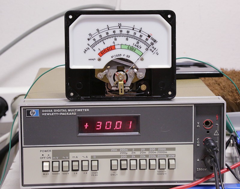
This old Hewlett Packard 3465A is the king when it comes to fine DC current measurements. At 200uA range it has 10nA resolution, so two digits behind the decimal point. They are hard to find in very good condition now, because many were scrapped for the high gold content. Also many have the 'option2' which means a battery pack is inside, which is always leaky, unless somebody was so wise to remove it in time. So when you have a good one, you will never sell it again. I have a 6.5 digit 34401A from Hewlett Packard, but the 34401A will only indicate 30.0X. With 'X', I mean a continuous changing number, which you can not even read. When I set 34401A for 'averaging' it becomes very slow, and the last number can be read, but still is changing. Like when it changes slowly like: 4....2....6....4.... the meter tries to tell you it is probably 3. So the last digit is just a software constructed fake. Not so with 3465A. It can measure with a stabile 10nA resolution, immediately after switch on. Though it needs to warm up for 30 minutes for full precision. (Same as 34401A). Another good reference meter is the analog Multizet from Siemens, but there are many versions, you need the one whit 30uA full scale, and they are hard to find undamaged. (Damage means linearity errors). I am luck to have a good Multizet, but the Hewlett Packard 3465A is the best I ever saw, for measuring in steps of 10nA. Moreover, there are no digital calibration parameters stored inside, and calibration is mainly by setting the 10Volt internal reference precisely, with some switches for coarse, and a potmeter for fine.
AVO Meter damping capacitor. Inside the switch on the right side of the panel of the Mk4, (the switch with 'gas test' on it) you will find the a capacitor of 10uF hidden, which is wired in parallel with the meter. This capacitor is never used since 50 years, or only when you use the tester, the voltage becomes 100mV at full meter scale, and that is the same as unused. To keep an electrolytic capacitor in condition, you need at the voltage to format the layers inside electrically, which is a simple electrochemical reaction, and from the voltages of the Reduction Potentials, you can see aluminum needs 1.6 Volts to begin to do something. So 100mV does nothing. And these capacitors are always totally dead. It's impedance is very high, and it can not protect the meter any more. This is actually an important reason why so many meters are damaged. My advise is, cut out the old capacitor from within the switch, and do not try to solder in a replacement back inside the switch. It has too little space in there, and you can damage something. Better is, simply mount the replacement cap across the panel meter directly. There is lots of space there. As a replacement I recommend a hermetic, wet tantalum type. Wet, means it has acid fluid inside, same as all electrolytic caps. The hermetic tantalum types are not made any more, but can be found as Russian NOS for prices like 8...15 Euro. These stay good when stored for ever.
The Protection diodes. There are great misunderstanding about those. Inside the switch, you will also see these two big, gold plated power diodes. You may think: Such old fashioned junk! You assume there is something better today, and you may be tempted to replace then by tiny modern diodes, like 1N4148, or Schottky or perhaps even some Germanium diodes. You better don't do that. Power diodes have simple very large chips inside. By cutting such a chip in smaller pieces, you would get lower power diodes. This is really how small diodes are made! Cut large diodes in pieces. So consider a power diode as many small diodes in parallel. Now here comes the effect. Don't try to argue against it, before you have tried this out yourself. When you put several diodes in parallel, the forward voltage at the same current will become lower. So using such a 10 Ampere diode to protect a 100mV instrument works much better as using a 10mA diode. You may find this interesting: A silicon diode below a certain voltage becomes non conductive. We all know that. Provided it doesn't leak of course. Well those gold plated diodes inside are still high quality today. So at 100mV they are in the mega ohms range. Somewhere around 300mV they begin to pull a few uA already, at a voltage level where a very small silicon diode like 1N4148, pulls no current yet. So those BIG diodes do a better job than tiny ones. Germanium diodes may seem better because of their lower forward voltage, but these have a very unusual property, that is unknown to most people. These stay diodes at any voltage, no matter how low. So at 100mV there is simply some small conduction already, and at 100mV and at 1mV or 1uV as well. So they protect the meter, but they give a scale error. Now you will say, any multi meter, has Germanium protection diodes inside. However, this small conductance is compensated by the scale. (Rather the scale unlinearity). In the AVO tester, they obviously preferred those big silicon power diodes, I guess that's because there was room enough. Seeing this, I assume this was the better choice, as these gold plated power diodes were sure more expensive than Germanium small signal diodes.
A damaged meter, initially may just look like a good meter. Lets assume a measurement at the 25mA scale. The linearity being gone, that would result for instance in a 17mA tube to indicate 19mA. Yet at 25 the indication is correct, 25mA. Lets say we have a linearity error of 10% it can easily be the case. The problems all chain up. Let me explain how this chains up. So you measure the indicated transconductance at 10% too low plate current, and transconductance comes out wrong, BUT.... this wrong result you measure also with 5% or 10% error. Next thing, you calibrated the mains wrong, and that gives quite an error. Just make a setting for a random tube, and observe what clicks of the main switch will do, and 2 clicks is much less than 10% variation on the mains. So you see now, the one error caused the other. Then comes calibration, this was done by yourself, or the one before, you, or the one before that one. It was calibrated with a faulty meter. So you see, this initially small error comes in several times, and the result is much larger as one may think.
Here are some quick meter tests you can do, to see if your meter is ok.
- Meter Balance.
This is an easy one, and you don't need to open the tester. Put in a random tube and set the meter for 25% of full scale. Simply adjust the grid voltage for that. Gently tap the meter before each measurement. Wait until the tester and the tube get stabile. Now, put the tester on it's right side, and read again. Then set it on the left side and read again. Then hold the whole tester such that the meter is in a horizontal plane, and read again. All measurements must be identical ideally. A definitely bad meter will read different, and the Mk4 was definitely not manufactured that with such an error. Then repeat at 50% and 75% of full scale. I can't tell where the limit is is for a 'just' good meter, but a good one will not change more than let's say 15%. At a fail: The meter has a linearity error, usually caused by bad needle balance, which is a result of coil deformation. (mechanical damage - if needle was hammered into the right corner violently). Even so, a person doing a good job on meter balancing can adjust this by an artificial off balance. So when the meter at 50% of full scale, indicates only 46%, this can be brought back to 50% again, by off balancing the needle on purpose. That is why off balance must always be judged together with linearity, and a meter may not seem in perfect balance, but yet be quite linear. - STICKY METER
For this, just slowly move the meter needle from 0...100 on the 100 scale. This can be done with some test tube. If the needle suddenly makes a small jump, always at the same position, this is the typical sticky needle problem, and you have a magnetic particle inside the coil gap. Moreover the particle can move to another position, or sometimes be more troublesome that at other times. - Friction
This can be seen by taking some tube and set it for various plate current . When you tap on the meter, the needle may not move more than 1 divisions of the 100mA scale. As each division is 2mA, this is 2% of full scale. For a fine measurement, you need to tap the meter anyway, but the change should be small, like above. - STICK-SLIP EFFECT
This is the combination of all problems, and may not be more than 3% of full scale. This a a lot of course. As it represents an error of 3% at full scale, but already 6% at 50% of full scale. For that reason AVO says the meter is unspecified below 10% of full scale.
Normally I can adjust a meter better than that.
- IMPEDANCE
 Any wrong impedance will give a false reading, since the meter impedance is part of some attenuator circuits, inside the AVO tester.
 Warning: The meter of Mk3, Mk4, CT160 is 30uA and overload is only factor 10. So you will probably damage it when you test the impedance using 1mA, like 99% of all ohms meters do. Also the expensive ones do so. And yes, also Fluke. However some can do 100uA if you set it for higher resistance. Like set it for 100k or so.
So do not simply connect an Ohms meter to your AVO meter. The result is likely the needle hammers violently in the right corner, and the coil is deformed. The meter probably still works, but linearity is gone, due to mechanical deformation of coil and needle.
In case you feel skilled enough, connect a (discharged!) foil capacitor of 20...100uF to the meter. This protects the meter reasonably.
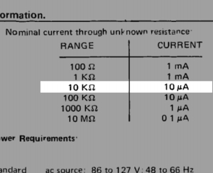 If the ohms meter you want to use, is auto range, you can not use it. These all start with 1mA, to see what happens, and only go to 100uA only if needed. The AVO meter can damage 1mA! So you need to be sure it is not auto range, and it tests the device under test with 100uA. To see if this is really so, use second meter, and set it to 1mA full scale. Just measure the impedance of this second (ampere) meter, using the ohms meter, and you will now see the test current. If 100uA indeed, you are safe. THIS you can connect now to the AVO meter. Before you do, test it with a 1 Mega ohms resistor in series. Like this the AVO meter will move just a small bit. This is needed to see the direction in which the needle moves. Make sure the needle moves to the LEFT. If so, repeat without the 1 Mega ohms resistor, and now you measure the meter impedance without damaging it. Really, many good AVO meters were damaged, while testing the impedance uncareful.
The impedance must be 3250 +/- 1% by the factory manual, but... read the next part!
- TEMPERATURE COMPENSATION
What is the effect of this? At first, there is no effect on the mains cal ~ mark, because the panel meter is supplied by a calibrated current source of exactly 27uA during this test. (A current source is no voltage source) So a change in temperature will significantly (!) change the meter impedance, but this will not change the meter current, because this current is generated outside of the panel meter by a current source. So... my compliments for the designers, this was really well done. The same applies for the leakage resistance, it is measured by serializing the leakage resistance of the tube with the same 27uA current source. So at a short you get a 'zero' ohms at the meter scale, which is at 27uA.
So, when DOES this temperature coefficient matter? Well, the answer is: For the plate current measurement! This measurement is done by measuring the voltage across this curious 199 ohms resistor inside, and... it is a hand wound resistor. Made of a normal resistor, and in parallel is copper wire wound. So you see the same principle as the meter + 10k in parallel.
Here I see the explanation: The assembly, panel meter + inside resistor of the tester, has the same temperature coefficient as the current sense resistor inside, which is also a copper wire + resistor in parallel. This makes the whole temperature perfectly temperature compensated. This explanation is not so hard, but it took me a very long time to find it out I always wondered why they wired a 199 Ohms resistor by hand, when they could have put two 100 Ohms in series too. - LINEARITY
Linearity testing really requires a precise current meter. You may be able to simulate one from a 10k resistor, and measure the voltage across it, but I see some options here to get errors. It should be clear, when you have a linearity error, you also doing the mains calibration wrong, since the mark is at appr '90mA'. Further, you can not measure transconductance precise, since for that you need to set the needle for '1' at the red/green scale, which mark is at 21uA. - METER GLASS
Is the glass loose, you will get dirt particles inside. This will cause a sticky meter, it is a matter of time. Magnetic dust is part of normal dust a building. These extremely small magnetic particles will creep inside the meter, logically into the direction of highest magnetic field force. This place is the magnetic gap where the coil moves, so here they will collect. Many small parts can cluster and optically it looks like a dust layer, and this gives friction at one or more positions of the needle. A larger particle will cause the needle to stick at one position. This is definitely no DIY job, to remove it. Do not try to blow this out with air. The magnetic particles will further stick, because air pressure on such a microscopic part is too small, but air pressure can deform the coil and hair springs. In most cases it requires the meter to be disassembled - IN GENERAL
The above warnings may seem like overdoing it, but I can not be repeat enough, a bad meter is the #1 cause for problems with your AVO, and most meters I get here, are damaged by bad repair. - The solution for a bad meter
Send in for repair or replace, useually works out. I was able to repair most meters. Keep in mind a good meter has a market value of 700 Euro. Given a Mk4 ranges from 1600 to 4000 Euro, depending on it's precision and condition, this explains the value of such a meter. - A New made, replacement meter
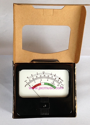 This can be supplied for all testers. The original old movement, we were the last company being able to purchase them, and this definitely impossible now. However we can build them from available new or NOS meters, which we adapt for electrical specifications, and copy the scale. We prefer tout band meters, they are a class above the original meters, as the coil is suspended friction-free, and also such meters are much more overload proof. For a price, search the complete price list electronically for the word: "AVO" and the order number belonging to it